
Signal Conditioning and Data Acquisition: From Sensor Signal to Digital Value
On this page
Most sensors do not produce a signal a control system can use directly. A thermocouple gives a few millivolts, a strain gauge changes resistance by a fraction of a percent, a vibration sensor produces a fast AC signal. Signal conditioning turns these into clean, standard signals; data acquisition converts them to digital values at the right rate and resolution. Errors introduced here cannot be corrected later by software.
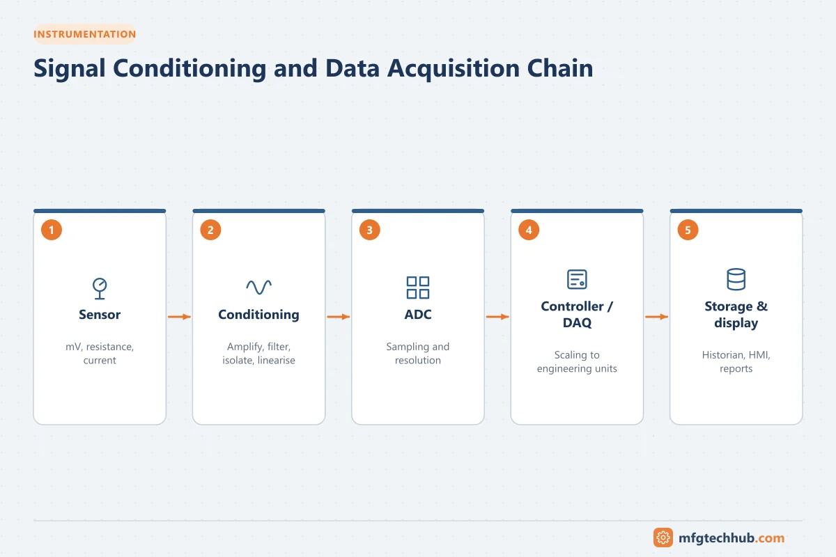
The signal chain
| Stage | Purpose | Typical implementation |
|---|---|---|
| Sensor | Converts a physical quantity to an electrical signal | Thermocouple, RTD, strain gauge, piezo sensor |
| Excitation | Supplies the sensor with voltage or current where needed | Bridge excitation, RTD current, IEPE supply |
| Amplification | Raises small signals to a usable level | Instrumentation amplifier |
| Filtering | Removes noise outside the signal band | Low-pass filter, 50/60 Hz rejection |
| Isolation | Breaks ground loops and protects equipment | Galvanic isolators, isolated I/O |
| Linearisation and compensation | Corrects non-linear sensors, compensates cold junction | Transmitter electronics or I/O card |
| Conversion to a standard signal | Transmits robustly | 4–20 mA, 0–10 V, digital fieldbus |
| Analog-to-digital conversion | Produces a digital number | I/O card ADC |
| Scaling | Converts counts to engineering units | Controller or I/O configuration |
Standard signals
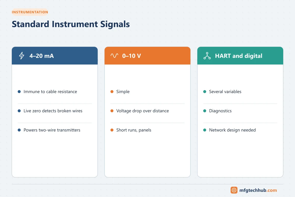
| Signal | Strengths | Limitations |
|---|---|---|
| 4–20 mA | Immune to cable resistance, “live zero” detects broken wires, powers two-wire transmitters | One variable per pair unless HART is used |
| 0–10 V / 1–5 V | Simple | Affected by cable voltage drop and noise over distance |
| HART | Digital data over 4–20 mA | Slow |
| Fieldbus, Ethernet-APL | Many variables, diagnostics | Network design and skills |
Scaling a 4–20 mA signal: value = LRV + (I − 4) ÷ 16 × (URV − LRV). For 12 mA on a 0–200 °C range: 0 + (8 ÷ 16) × 200 = 100 °C. Check values with the 4–20 mA Calculator.
Conditioning functions in detail
- Cold-junction compensation (CJC): a thermocouple measures the difference between its hot junction and the terminals; the terminal temperature must be measured and compensated. See Thermocouples.
- Lead-wire compensation: 3- and 4-wire RTD connections cancel cable resistance. See RTDs and Thermistors.
- Bridge completion and excitation for strain gauges and load cells. See Load Cells.
- Isolation between field and control system, and intrinsic safety barriers or isolators for hazardous areas.
- Damping and filtering: reduce noise but add lag; do not filter signals used for protection without understanding the delay.
Analog-to-digital conversion
| Parameter | Meaning | Practical note |
|---|---|---|
| Resolution | Number of bits of the ADC | A 16-bit converter divides its range into 65,536 steps; effective resolution is lower with noise |
| Sampling rate | Samples per second | Must suit the signal: slow for temperatures, fast for vibration |
| Nyquist criterion | Sample at more than twice the highest frequency of interest | In practice, sample several times higher |
| Aliasing | High frequencies appearing as false low frequencies | Use anti-aliasing filters before sampling |
| Update time | How often the controller sees a new value | Depends on I/O card, network and scan time |
Data acquisition systems
| Type | Typical use |
|---|---|
| PLC and DCS I/O | Control and monitoring of plant signals |
| Stand-alone DAQ devices | Tests, commissioning, troubleshooting, laboratory work |
| High-speed DAQ | Vibration, acoustics, transient events |
| Data loggers | Unattended recording, remote sites; see Data Logging and Remote Monitoring |
| Wireless sensor systems | Monitoring points where cabling is expensive; see Wireless Sensor Networks |
Troubleshooting signal problems
| Symptom | Likely cause | First check |
|---|---|---|
| Value jumps when a motor or drive starts | Ground loop, poor shielding, cable routing near power | Shield earthing at one end, segregation, isolator |
| Thermocouple reads a few degrees wrong | CJC error, wrong type selected, wrong extension cable | Type configuration, cable colour code, terminal temperature |
| RTD reads high | 2-wire connection or lead resistance | Wiring configuration |
| Value slow to respond | Excessive damping or filtering | Transmitter damping and I/O filter settings |
| Periodic oscillation at low frequency | Aliasing from vibration or mains | Anti-aliasing filter, sampling rate |
| Value stuck at an end of range | Broken wire, overrange, wrong scaling | Loop current, NAMUR NE 43 failure levels |
See Grounding and Earthing, EMI/EMC and Instrument Troubleshooting.
Frequently asked questions
What is signal conditioning?
The processing of a raw sensor signal (excitation, amplification, filtering, isolation, linearisation, compensation) to produce a clean, standard signal that a control or data acquisition system can use.
Why is 4–20 mA used instead of 0–20 mA?
The 4 mA “live zero” lets the system tell a real zero reading from a broken wire, and it leaves enough current to power two-wire transmitters.
How fast should a signal be sampled?
At more than twice the highest frequency of interest (the Nyquist criterion), and in practice several times higher, with anti-aliasing filters to remove higher frequencies.
Key takeaways
- Signal conditioning prepares raw sensor signals; data acquisition digitises them.
- 4–20 mA remains the robust standard; HART and digital networks add data and diagnostics.
- Choose resolution, sampling rate and filtering to suit the signal.
- Most signal problems come from grounding, shielding, configuration and wiring.
Related tutorials
Before you apply this in a plant: this article is for education. Always check the current edition of the relevant standards, the manufacturer's documentation for your exact product and version, and your site's procedures. Safety-related work needs qualified personnel. See our editorial policy.