
Instrumentation and Electrical (I&E) Systems in Industry: What They Cover and How They Fit Together
On this page
In most plants, instrumentation and electrical (I&E) is one discipline with two halves. Instrumentation measures the process and acts on it: transmitters, analysers, switches, control valves and the signals that connect them to control systems. Electrical supplies and protects the power that everything runs on: transformers, switchgear, motor control centres, drives, UPS and earthing. Control systems (PLC, DCS, SCADA) sit on top of both.
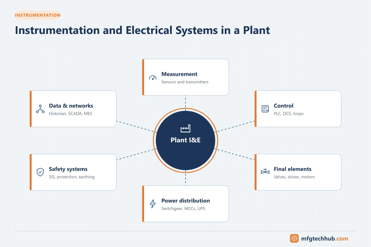
What the I&E discipline includes
| Area | Typical scope | Series chapter |
|---|---|---|
| Measurement | Temperature, pressure, flow, level, analysers, force, vibration | Chapter 2 |
| Final control elements | Control valves, on/off valves, positioners, drives | Control Valves |
| Signals and networks | 4–20 mA, HART, fieldbus, wireless, Ethernet | Signal Conditioning |
| Power distribution | Transformers, switchgear, MCCs, cables | Chapter 3 |
| Motors and drives | Induction motors, VFDs, soft starters, protection | Types of Motors |
| Protection and safety | Breakers, RCDs, earthing, surge protection, hazardous areas | Electrical Hazard Prevention |
| Backup power | UPS, generators | UPS and Battery Backup |
| Test and maintenance | Calibration, loop checks, condition monitoring | Chapter 6 |
How I&E connects to control systems
A single control loop shows the whole chain: a transmitter (instrumentation) measures a flow, a 4–20 mA signal travels through junction boxes and marshalling to an I/O card of a PLC or DCS (control system), the controller calculates an output, and an analog output drives a control valve positioner (instrumentation). All of it runs on 24 V DC and 230/400 V AC supplies (electrical) with UPS backup, earthing and surge protection. A fault in any link, from a blocked impulse line to a failed power supply, stops the loop. See How a Factory Works.
Key I&E project deliverables
| Deliverable | Content |
|---|---|
| Instrument index | Every instrument with tag, service, range, type |
| Instrument data sheets | Specification for purchasing each instrument |
| P&IDs (input) | Instruments and loops on the process drawings; see P&ID Introduction |
| Loop diagrams | Wiring from device to control system (ISA-5.4) |
| Hook-up drawings | Installation details: impulse lines, mounting |
| Cable schedules and block diagrams | Cables, junction boxes, routing |
| Single-line diagrams | Electrical distribution from supply to loads |
| Load list and cable sizing | Power demand, cable and protection selection |
| Hazardous area classification and Ex register | Zones and equipment protection |
| Earthing and lightning protection design | Protective and functional earthing |
Who does what
| Role | Focus |
|---|---|
| Instrument engineer | Selection, specification, hook-ups, loops, calibration strategy |
| Electrical engineer | Power distribution, protection, motors, earthing, hazardous areas |
| Control systems engineer | PLC, DCS, SCADA configuration and integration |
| I&E technicians | Installation, loop checks, calibration, maintenance and fault finding |
| Process and safety engineers | Requirements, hazard studies, safety functions |
See the Automation Engineer Roadmap for career paths.
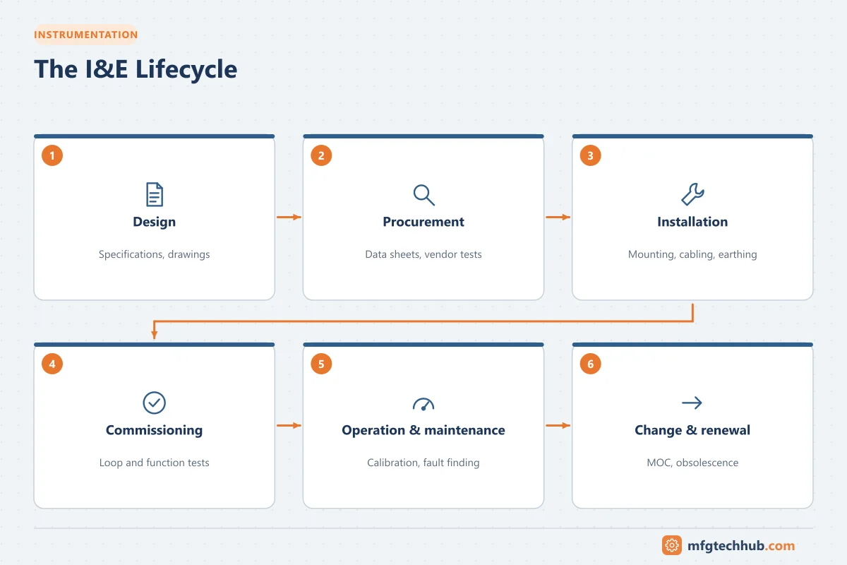
The I&E lifecycle
- Design: requirements from the process, hazard studies, specifications, drawings.
- Procurement: data sheets, vendor documents, factory tests.
- Installation: mounting, cabling, terminations, earthing, inspection.
- Commissioning: insulation and continuity tests, loop checks, functional tests. See Loop Calibrators.
- Operation and maintenance: calibration, preventive and predictive maintenance, fault finding.
- Modification and renewal: management of change, obsolescence, upgrades.
See Instrumentation and Electrical Best Practices.
How this series is organised
| Chapter | Topics |
|---|---|
| 1. Introduction | This overview, measurement and control, standards, traditional vs modern systems, I&E safety |
| 2. Measurement fundamentals | Accuracy, calibration, signals, temperature, pressure, flow, level, force, control, P&IDs |
| 3. Electrical and power | Power measurement, motors and drives, protection, distribution |
| 4. Electronic instruments | Test equipment, sensors, identification, vision, EMC |
| 5. Automation and control | PLC, SCADA, DCS |
| 6. Maintenance | Calibration programmes, troubleshooting, condition monitoring |
| 7. Emerging trends | Smart instruments, AI, 5G, digital twins, sustainability |
| 8. Applications | Implementation examples |
| 9. References | Books, websites, best practices |
Frequently asked questions
What does I&E stand for?
Instrumentation and electrical: the discipline covering measurement and control devices and their signals (instrumentation) and power distribution, motors, protection and earthing (electrical).
What is the difference between instrumentation and control engineering?
Instrumentation focuses on measuring and actuating devices and their installation; control engineering focuses on the logic and control strategies in PLCs and DCS. In practice the roles overlap and are often combined as “I&C”.
Which documents does an instrumentation engineer produce?
Typically the instrument index, data sheets, loop diagrams, hook-up drawings, cable schedules and calibration requirements, working from the P&IDs.
Key takeaways
- I&E combines instrumentation (measure and act) and electrical (power and protect).
- Control systems depend on both; a fault anywhere in the chain stops the loop.
- Clear deliverables (index, data sheets, loops, single-lines) make projects and maintenance manageable.
- The same equipment must be looked after across design, commissioning, operation and change.
Related tutorials
Before you apply this in a plant: this article is for education. Always check the current edition of the relevant standards, the manufacturer's documentation for your exact product and version, and your site's procedures. Safety-related work needs qualified personnel. See our editorial policy.