
Preventive Maintenance of Instruments: Calibration Intervals and Periodic Testing
On this page
Instruments drift, age and fail. A pressure transmitter that reads 2% high, a blocked impulse line, or a level switch that no longer trips can lead to poor quality, wasted energy or a safety incident. Preventive maintenance (PM) of instrumentation keeps measurements trustworthy through planned calibration, inspection and testing, while avoiding unnecessary work on instruments that are stable.
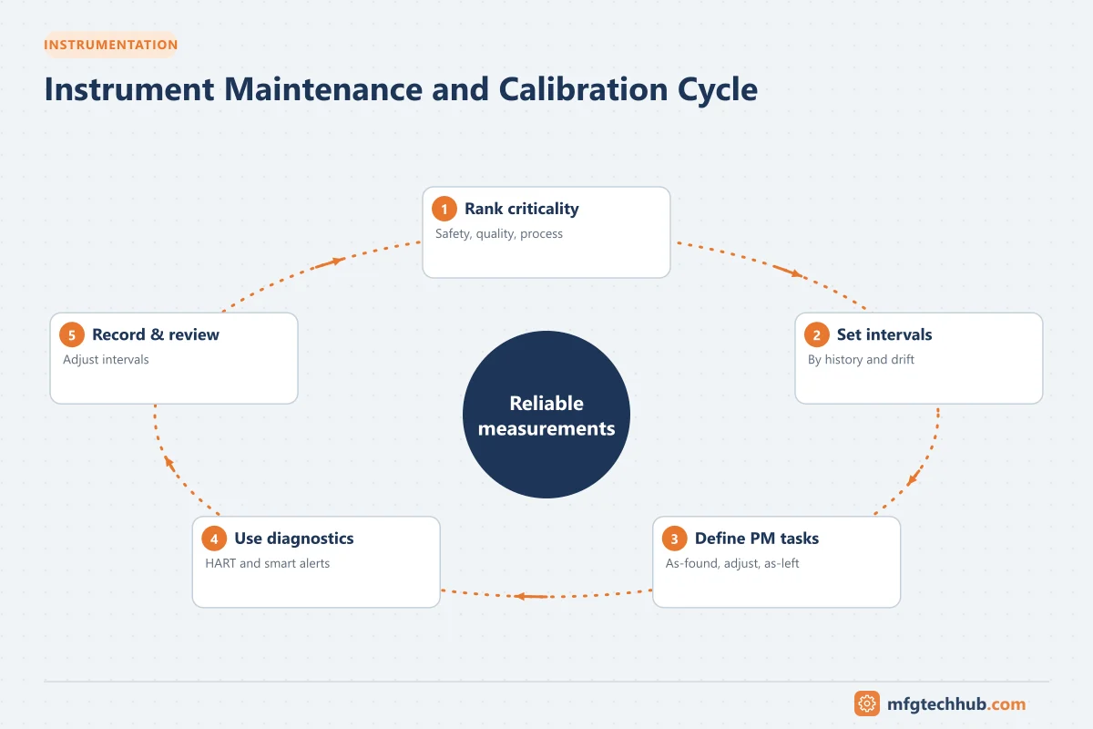
Types of instrument maintenance
| Strategy | Description | Best for |
|---|---|---|
| Corrective (run to failure) | Repair after failure | Non-critical indicators with no consequence |
| Preventive (time-based) | Calibrate and inspect at fixed intervals | Critical and regulatory instruments |
| Condition-based / predictive | Act on diagnostics, drift trends and condition data | Smart instruments with diagnostics, high-value assets |
| Proof testing | Test safety functions to reveal hidden failures | Safety instrumented systems and critical alarms |
A good program combines these strategies based on criticality.
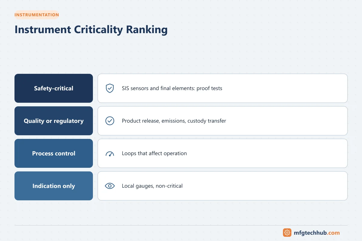
Step 1: Rank instruments by criticality
Not all instruments deserve the same effort. Rank each instrument by the consequences of an incorrect reading:
| Criticality | Examples | Typical approach |
|---|---|---|
| Safety-critical | Instruments in safety instrumented functions, fire and gas detection | Proof testing at intervals set by the SIL verification (IEC 61511) |
| Quality or regulatory | Product quality, custody transfer, emissions monitoring, pharmaceutical GMP | Fixed calibration intervals and full documentation |
| Process control | Important control loops, energy measurement | Periodic calibration or condition-based checks |
| Indication only | Local gauges with no control function | Inspection or run to failure |
Step 2: Set calibration intervals
Calibration intervals should be based on evidence, not habit. Consider:
- Manufacturer’s stability specification
- Criticality and required accuracy
- Process conditions: temperature cycling, vibration, corrosive or dirty fluids
- Historical as-found data: if an instrument is always found within tolerance, the interval may be extended; if it is often out of tolerance, shorten it
- Regulatory requirements
A common starting point is 12 months for important instruments, adjusted using as-found results. Always record as-found data before adjusting; otherwise there is no evidence of drift.
Step 3: Define what each PM task includes
Calibration
Test at several points across the range (typically 0, 25, 50, 75 and 100%), record as-found and as-left values, and adjust if outside tolerance. See Loop Calibrators for Process Control.
Inspection
- Physical damage, corrosion and missing covers
- Condition of cable glands, conduits and seals
- Impulse lines: leaks, blockages, heat tracing
- Mounting, vibration and supports
- Hazardous area equipment integrity (Ex inspections to IEC 60079-17)
Functional testing
- Alarms and trips activate at the correct set point
- Switches operate and reset correctly
- Control valves stroke fully and fail to the safe position
Proof testing of safety functions
Safety instrumented functions have failure modes that only appear on demand. Proof tests simulate or create the trip condition end to end, from sensor to final element, at the interval assumed in the SIL calculation. Partial stroke testing of shutdown valves can reveal some failures between full tests.
Step 4: Use smart instrument diagnostics
Modern HART, fieldbus and wireless instruments provide diagnostics such as sensor failure, plugged impulse line detection, electronics faults and configuration changes. NAMUR NE 107 standardizes status signals:
| NE 107 status | Meaning |
|---|---|
| Failure | Output is invalid |
| Function check | Output temporarily invalid due to work on the device |
| Out of specification | Operating outside specified conditions |
| Maintenance required | Still valid, but maintenance needed soon |
Asset management systems collect these diagnostics centrally, so technicians can focus on devices that actually need attention.
Step 5: Keep good records
For every task, record:
- Instrument tag, range and tolerance
- Date, technician and reference equipment (with its calibration certificate)
- As-found and as-left results
- Adjustments made and observations
- Next due date
Calibration management software or a CMMS makes it easy to trend drift and plan work. See MES Data Collection and Integration for how maintenance and production data can be linked.
Step 6: Improve continuously
- Review instruments that are repeatedly found out of tolerance and address root causes (wrong instrument type, poor installation, harsh process).
- Extend intervals for consistently stable instruments.
- Remove PM tasks that add no value.
- Update procedures after incidents and near misses.
Common mistakes
- Adjusting instruments without recording as-found values
- Using reference equipment that is not more accurate or not in calibration
- Calibrating the transmitter but not checking the control system scaling
- Leaving bypasses or forces in place after testing
- Treating all instruments the same regardless of criticality
Key takeaways
- Rank instruments by criticality and match the maintenance strategy to the risk.
- Base calibration intervals on as-found history, manufacturer data and requirements.
- Proof test safety functions end to end at the intervals assumed in SIL calculations.
- Use smart diagnostics (NAMUR NE 107) and good records to move toward condition-based maintenance.
Related tutorials
Before you apply this in a plant: this article is for education. Always check the current edition of the relevant standards, the manufacturer's documentation for your exact product and version, and your site's procedures. Safety-related work needs qualified personnel. See our editorial policy.