
Thermocouples: Types, Cold-Junction Compensation, Installation, Calibration and Troubleshooting
On this page
A thermocouple is two wires of different metals joined at one end. When the joint (the hot or measuring junction) is at a different temperature from the other end (the reference or cold junction), a small voltage appears, a few tens of microvolts per degree. Thermocouples are rugged, cheap, fast and cover very wide temperature ranges, which is why they dominate furnaces, kilns, exhaust gases and high-temperature processes. Their weak points are small signals, lower accuracy than RTDs and sensitivity to wiring mistakes.
How a thermocouple measures temperature
- The voltage depends on the difference between the measuring junction and the reference junction (the terminals at the transmitter or I/O card).
- The instrument therefore measures the terminal temperature (for example with a built-in sensor) and adds the corresponding voltage: cold-junction compensation (CJC).
- The voltage–temperature relationship is non-linear and is converted using the standard reference tables for each type (IEC 60584-1).
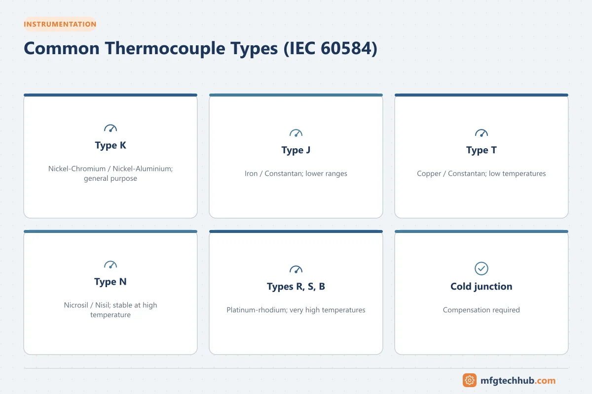
Common thermocouple types
Approximate usable ranges; exact tolerance ranges depend on type, class and wire diameter (see IEC 60584-1):
| Type | Materials (positive / negative) | Approximate range | Typical uses and notes |
|---|---|---|---|
| K | Nickel-chromium / nickel-aluminium | About −200 to 1,200 °C | General purpose, most widely used; drift possible in some temperature bands |
| J | Iron / copper-nickel | About −40 to 750 °C | Older installations, plastics; iron leg oxidises |
| T | Copper / copper-nickel | About −200 to 350 °C | Low temperatures, food, laboratories |
| E | Nickel-chromium / copper-nickel | About −200 to 900 °C | Highest output per degree of common types |
| N | Nickel-chromium-silicon / nickel-silicon | About −200 to 1,200 °C | More stable than K at high temperature |
| R, S | Platinum-rhodium / platinum | Up to about 1,600 °C | High temperature, high stability, expensive |
| B | Platinum-rhodium / platinum-rhodium | About 600 to 1,700 °C | Very high temperatures; low output below about 50 °C |
Tolerance classes (IEC 60584-1)
For type K, for example, Class 1 tolerance is ±1.5 °C or ±0.004 × |t| (whichever is greater) over its range, and Class 2 is ±2.5 °C or ±0.0075 × |t|. At 800 °C, Class 2 means ±6 °C. When better accuracy is needed at moderate temperatures, an RTD is usually the better choice. See RTDs vs Thermistors.
Cables and colour codes
- Use extension cable (same alloys as the thermocouple) or compensating cable (different alloys with matching output over a limited temperature range) from the sensor to the instrument. Ordinary copper cable introduces errors wherever there is a temperature difference.
- Keep polarity correct; a reversed pair in the middle of a run produces errors that change with ambient temperature.
- IEC 60584-3 defines colour codes: the positive conductor has the type colour (for example green for K, black for J, brown for T, pink for N, orange for R and S) and the negative is white. North American (ANSI/ASTM) codes differ, with a red negative lead, so check which standard your plant uses.
Installation
| Item | Good practice |
|---|---|
| Thermowell | Protects the sensor and allows removal under pressure; check wake frequency (ASME PTC 19.3 TW) for high velocities |
| Immersion length | Sufficient to avoid heat conduction errors along the well |
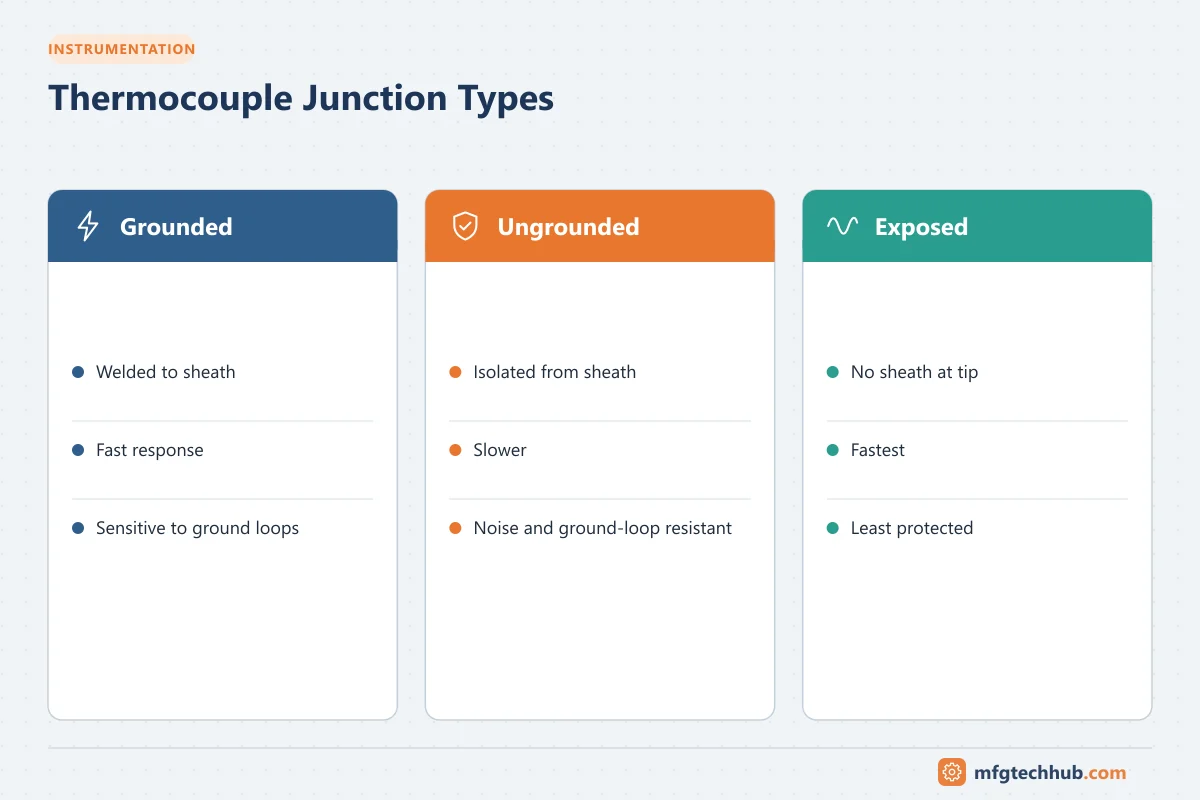
| Response time | Grounded junctions and small diameters respond faster; thermowells slow response |
| Junction type | Grounded (fast, noise-sensitive), ungrounded (isolated), exposed (fastest, least protected) |
| Transmitter location | Head-mounted transmitters shorten the thermocouple wiring and convert to 4–20 mA |
| Noise | Twisted, shielded cable; isolated inputs |
Calibration
| Method | Use |
|---|---|
| Comparison in a dry block or bath | Compare with a reference sensor at several temperatures |
| Fixed points | Laboratory reference calibration (for example freezing points of metals) |
| Loop check with a simulator | Checks transmitter, CJC and I/O by injecting millivolts; does not check the sensor |
| In-situ comparison | Reference sensor in an adjacent test well |
Thermocouples can drift in service (especially at high temperature) and are often replaced rather than recalibrated. See Calibration and Traceability and Loop Calibrators.
Troubleshooting
| Symptom | Likely cause | First check |
|---|---|---|
| Reads room temperature | Short circuit forming a new junction near the terminals | Wiring and connections |
| Error changes with ambient temperature | Copper or wrong-type cable, reversed extension pair, CJC fault | Cable type, polarity, CJC reading |
| Wrong type configured | Output interpreted with wrong table | Type setting in transmitter or I/O |
| Upscale or downscale burnout | Open thermocouple | Continuity; burnout direction setting |
| Noisy reading | Grounded junction with ground loop, electrical noise | Isolation, shielding, junction type |
| Slow response | Heavy thermowell, air gap | Sensor fit in well, thermowell design |
| Gradual drift at high temperature | Metallurgical ageing | Compare with reference; replace |
Frequently asked questions
What is cold-junction compensation?
The correction for the temperature of the reference junction (the terminals). The instrument measures the terminal temperature and adds the corresponding thermocouple voltage so the result reflects the measuring junction temperature.
Which thermocouple type is most common?
Type K is the most widely used general-purpose type. Type N is often preferred for better stability at high temperatures; types R, S and B are used for very high temperatures.
Thermocouple or RTD?
Choose an RTD for better accuracy and stability at low and moderate temperatures; choose a thermocouple for high temperatures, fast response, vibration and lower cost.
Key takeaways
- Thermocouples measure temperature difference; cold-junction compensation is essential.
- Choose the type by range, stability and environment; K and N are common, R, S and B for very high temperatures.
- Use correct extension cable and polarity to avoid ambient-dependent errors.
- Expect drift at high temperatures; replace and verify rather than trusting old sensors.
Related tutorials
Before you apply this in a plant: this article is for education. Always check the current edition of the relevant standards, the manufacturer's documentation for your exact product and version, and your site's procedures. Safety-related work needs qualified personnel. See our editorial policy.