
EMI and EMC Testing in Industrial Electronics
On this page
Industrial plants are electrically noisy. Variable frequency drives, welders, contactors, radios and switching power supplies all generate electromagnetic interference (EMI). Electromagnetic compatibility (EMC) means equipment can operate correctly in its environment without being disturbed and without disturbing other equipment. Good EMC is the difference between a stable control system and one plagued by random resets, noisy signals and communication errors.
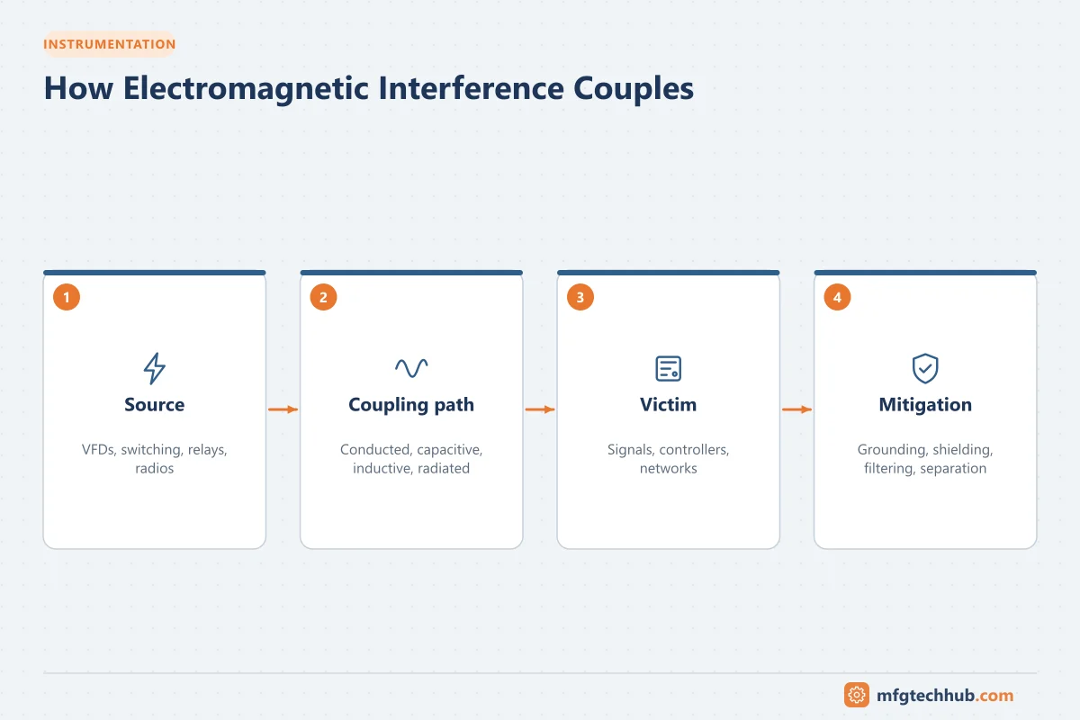
Emission and immunity
EMC has two sides:
- Emissions: interference that equipment produces, conducted along cables or radiated through the air
- Immunity (susceptibility): the ability of equipment to keep working when exposed to interference
A product is compatible when its emissions stay below limits and its immunity is high enough for the environment where it will be used.
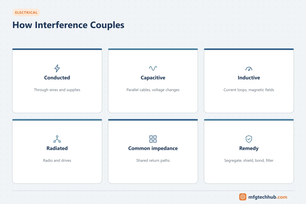
How interference couples
| Coupling path | Mechanism | Example |
|---|---|---|
| Conducted | Noise travels along power or signal conductors | VFD harmonics on the supply; noise on a shared 24 V supply |
| Capacitive | Voltage changes couple through stray capacitance | Motor cable running alongside a signal cable |
| Inductive | Changing currents create magnetic fields that induce voltages | High-current cables near sensor loops |
| Radiated | Electromagnetic waves travel through the air | Two-way radios near control panels |
| Common impedance | Circuits share a ground path | Signal returns sharing a ground with power loads |
Industrial EMC standards
| Standard | Scope |
|---|---|
| IEC 61000-6-2 | Generic immunity for industrial environments |
| IEC 61000-6-4 | Generic emissions for industrial environments |
| IEC 61326-1 | EMC for measurement, control and laboratory equipment |
| IEC 61800-3 | EMC for adjustable speed drives |
| CISPR 11 | Emission limits for industrial, scientific and medical (ISM) equipment |
In the European Union, equipment must meet the EMC Directive (2014/30/EU) to carry the CE mark, usually by showing compliance with harmonized standards. Other regions have their own requirements, such as FCC rules in the United States.
Common immunity tests (IEC 61000-4 series)
| Test | Standard | Simulates |
|---|---|---|
| Electrostatic discharge (ESD) | IEC 61000-4-2 | Discharges from people and objects |
| Radiated RF immunity | IEC 61000-4-3 | Radios, mobile phones, transmitters |
| Electrical fast transients (EFT/burst) | IEC 61000-4-4 | Switching of inductive loads such as contactors and relays |
| Surge | IEC 61000-4-5 | Lightning and large switching events |
| Conducted RF immunity | IEC 61000-4-6 | RF energy coupled onto cables |
| Power-frequency magnetic field | IEC 61000-4-8 | Fields near busbars and transformers |
| Voltage dips and interruptions | IEC 61000-4-11 (and -34 for higher currents) | Supply disturbances |
Each test has severity levels, and the product must meet a defined performance criterion (A: normal operation; B: temporary degradation with self-recovery; C: temporary loss of function requiring intervention or reset).
Emission tests
- Conducted emissions are measured on power ports, typically from 150 kHz to 30 MHz, using a line impedance stabilization network (LISN).
- Radiated emissions are measured with antennas, typically from 30 MHz to 1 GHz and above, in an anechoic chamber or open area test site.
Pre-compliance testing
Full EMC testing in accredited laboratories is expensive, so manufacturers often perform pre-compliance tests during development using spectrum analyzers, near-field probes, LISNs and ESD and burst generators. This finds problems early. See Function Generators and Spectrum Analyzers.
EMC in control panels and installations
Even compliant equipment can suffer interference if it is poorly installed. Good practices:
- Segregate cables: separate power, motor (VFD output) and signal cables, and cross them at right angles.
- Use shielded cables correctly: VFD motor cables with 360° shield terminations at both ends; analog signal shields as specified (often one end). See Grounding and Earthing Techniques.
- Bond metalwork: use a conductive mounting plate and short, wide bonding straps.
- Suppress inductive loads: fit RC snubbers or diodes on contactor and solenoid coils.
- Filter: use EMC filters on drives and sensitive supplies; ferrite cores on cables where needed.
- Isolate signals: use galvanic isolators for analog signals between systems.
- Separate zones inside the panel: keep drives and power components away from controllers and analog modules.
- Twist pairs: twisted-pair signal wiring reduces magnetic pickup.
Troubleshooting interference problems
| Symptom | Likely cause |
|---|---|
| Analog value jumps when a drive starts | Motor cable near signal cable, poor shielding, ground loops |
| PLC resets or communication errors when contactors switch | Missing coil suppression, EFT coupling on power supplies |
| Reading changes when a radio is keyed nearby | Poor RF immunity, unshielded cables, open cabinet doors |
| Random faults after lightning storms | Missing surge protection, poor bonding |
Use an oscilloscope and, where available, a spectrum analyzer or current probe to find the frequency and timing of noise, which often identifies its source.
Key takeaways
- EMC means equipment neither disturbs nor is disturbed by its electromagnetic environment.
- Interference couples through conduction, capacitance, induction, radiation and shared impedance.
- The IEC 61000-4 series defines immunity tests; CISPR 11 and IEC 61000-6-4 cover emissions.
- Good installation practices (segregation, shielding, bonding, suppression) prevent most real-world problems.
Related tutorials
Before you apply this in a plant: this article is for education. Always check the current edition of the relevant standards, the manufacturer's documentation for your exact product and version, and your site's procedures. Safety-related work needs qualified personnel. See our editorial policy.