
Digital Oscilloscopes for Industrial Troubleshooting
On this page
A multimeter tells you a single number. An oscilloscope shows how a signal changes over time, revealing noise, spikes, distortion, timing problems and intermittent faults that a meter cannot see. In industry, oscilloscopes are used to troubleshoot sensor signals, communication networks, drives, power supplies and control electronics.
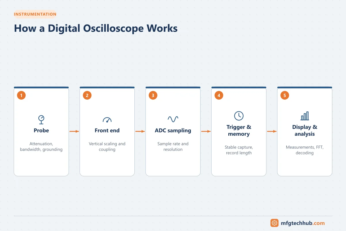
How a digital oscilloscope works
A digital storage oscilloscope (DSO) conditions the input signal, converts it to digital samples with a high-speed analog-to-digital converter (ADC), stores the samples in memory and displays them as a waveform:
Probe → Input amplifier/attenuator → ADC → Acquisition memory → Processing → DisplayThe vertical axis shows voltage and the horizontal axis shows time. Mixed-signal oscilloscopes (MSOs) add logic channels for digital signals, and many instruments decode serial protocols directly.
Key specifications
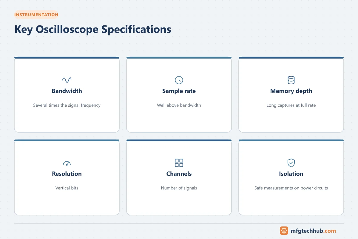
| Specification | Meaning | Practical guidance |
|---|---|---|
| Bandwidth | Frequency at which a sine wave is attenuated by 3 dB (about 30%) | Choose a bandwidth several times (commonly about 5×) higher than the highest frequency of interest |
| Sample rate | Samples per second (for example 1 GS/s) | Should be several times the bandwidth to reconstruct waveforms accurately |
| Record length (memory depth) | Number of samples stored per capture | Longer memory keeps a high sample rate over longer time windows |
| Vertical resolution | ADC bits (8, 10, 12 bits) | Higher resolution shows small signals and ripple more clearly |
| Channels | Number of inputs | Two or four analog channels are common |
| Isolation | Whether channels are isolated from each other and earth | Essential for many industrial and power measurements |
Triggering
The trigger tells the oscilloscope when to capture, so repeating waveforms appear stable and rare events can be caught.
- Edge trigger: when the signal crosses a voltage level on a rising or falling edge
- Pulse width trigger: catches glitches narrower or wider than expected
- Runt trigger: catches pulses that fail to reach full logic level
- Serial protocol triggers: trigger on specific messages (for example CAN, I²C, RS-485)
- Single-shot capture: records one event, useful for intermittent faults and startup sequences
Probes
| Probe type | Use |
|---|---|
| Passive 10:1 probe | General-purpose measurements referenced to ground |
| High-voltage differential probe | Measuring between two points that are not at earth potential, such as motor drive outputs or mains circuits |
| Current probe (clamp) | Measuring current waveforms without breaking the circuit |
| Active probe | High-frequency measurements with low loading |
Compensate passive probes before use by adjusting them on the oscilloscope’s calibration output until square edges look square.
Safety: the ground lead trap
On a typical bench oscilloscope, the probe ground lead is connected to protective earth through the mains cable. Clipping it to a point that is not at earth potential, such as the DC bus of a drive or a live mains conductor, creates a short circuit through the oscilloscope that can damage equipment and injure the user.
Safe practice:
- Use differential probes or isolated-channel oscilloscopes for non-earth-referenced measurements.
- Never “float” an oscilloscope by removing its earth connection.
- Use probes and instruments with an appropriate CAT rating (IEC 61010) for the measurement location.
- Follow electrical safety procedures and PPE requirements.
Industrial applications
Analog signal troubleshooting
Check 4-20 mA and voltage signals for noise, ripple and spikes that cause unstable readings in a PLC or DCS. Measure across a known resistor (for example 250 Ω) to see the current waveform.
Communication networks
Look at RS-485, CAN, PROFIBUS or other physical layers to check signal levels, reflections, termination problems and noise. A clean square wave with proper amplitude indicates a healthy network; ringing or rounded edges suggest termination or cable issues.
Power supplies and control power
Measure ripple on 24 V DC supplies, dips during load switching, and startup behavior.
Motor drives and power electronics
With differential probes and current probes, examine VFD output voltage and current, DC bus ripple, and switching transients.
Sensors and encoders
Check encoder pulses for missing counts, noise and correct phase relationships between A and B channels.
Handheld and portable oscilloscopes
Handheld, battery-powered oscilloscopes with isolated inputs are popular with field technicians. They combine oscilloscope, multimeter and sometimes recorder functions, and are rated for use on industrial electrical installations.
Tips for good measurements
- Start with auto-set, then adjust scales deliberately.
- Use the shortest possible ground connection for high-frequency signals.
- Use bandwidth limit filters to see low-frequency signals without high-frequency noise, and remove them to look for fast spikes.
- Use measurements and cursors for frequency, rise time, peak-to-peak and RMS values.
- Save screenshots and waveform data to document problems and repairs.
Key takeaways
- Oscilloscopes show how signals change over time, revealing faults that meters cannot.
- Bandwidth, sample rate and memory depth determine what the instrument can capture.
- Triggering is the key to capturing rare or intermittent events.
- Use differential probes or isolated oscilloscopes for non-earth-referenced industrial measurements.
Related tutorials
Before you apply this in a plant: this article is for education. Always check the current edition of the relevant standards, the manufacturer's documentation for your exact product and version, and your site's procedures. Safety-related work needs qualified personnel. See our editorial policy.