
P&ID Standards: ISA-5.1, ISA-5.4, ISO 14617 and ISO 10628
On this page
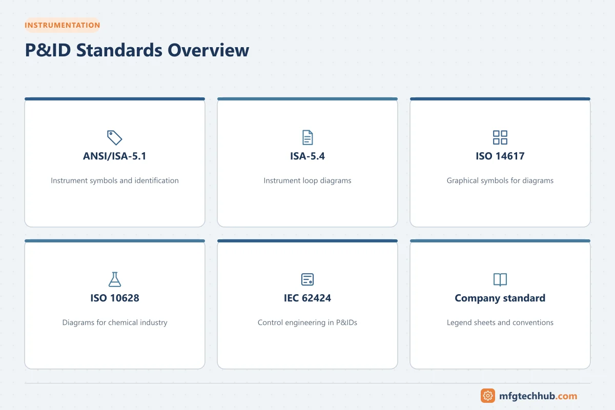
P&IDs are only useful if everyone reads the symbols the same way. Several international standards define the symbols, identification letters and document formats used in process plants. This article summarizes the most important ones and how they are used together in practice.
ANSI/ISA-5.1: Instrumentation Symbols and Identification
ISA-5.1 is the most widely used standard for instrument symbols and tags worldwide. It defines:
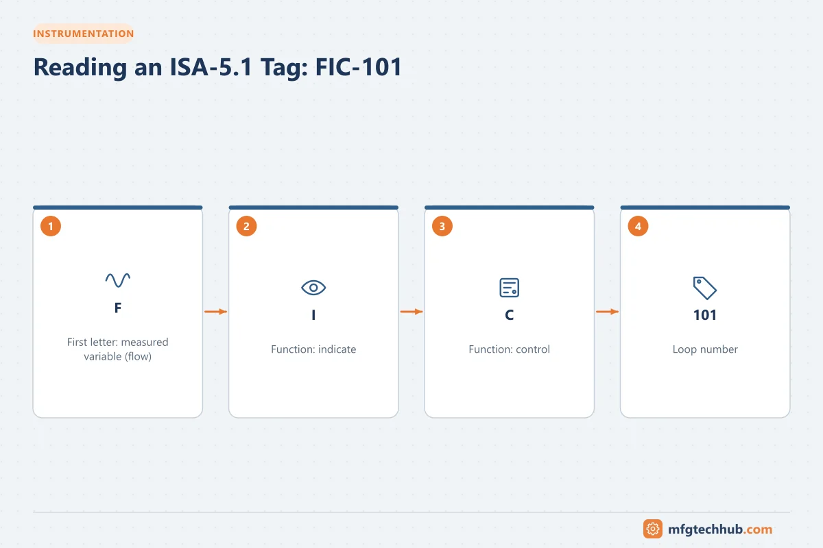
- Identification letters for measured variables and functions (for example FIC, PT, LSHH, TV)
- Loop numbering conventions
- Instrument symbols: circles for discrete instruments, circle-in-square for shared display/control, hexagons for computer functions, and diamond-in-square for PLC functions
- Location indication: field, central control room, local panel or behind the panel
- Line symbols for signals: pneumatic, electrical, software/data link, hydraulic and capillary
- Symbols for final control elements and actuators
The 2009 revision (ANSI/ISA-5.1-2009) updated the standard for modern systems, including symbols for shared and software functions. It also absorbed much of the content from the older ISA-5.3 on shared display and computer symbols.
See P&ID Symbols, Lines and Instrument Tags for the most common letters and symbols.
ISA-5.4: Instrument Loop Diagrams
ANSI/ISA-5.4 defines the content and format of instrument loop diagrams. While a P&ID shows a loop functionally, a loop diagram shows every connection needed to build and troubleshoot it:
- Field device, junction box, marshalling cabinet and control system terminals
- Cable and wire numbers, terminal numbers and polarity
- Power sources and grounding
- Instrument ranges, set points and I/O addresses
Loop diagrams are essential for commissioning (loop checks) and maintenance troubleshooting.
Other ISA-5 standards
| Standard | Subject |
|---|---|
| ISA-5.2 | Binary logic diagrams for process operations (interlock logic) |
| ISA-5.5 | Graphic symbols for process displays (HMI) |
| ISA-5.06.01 | Functional requirements documentation for control software applications |
ISO 14617: Graphical symbols for diagrams
ISO 14617 is a multi-part international standard for graphical symbols used in diagrams across many engineering disciplines, including symbols for valves, pumps, measurement and control functions. It aims to provide a consistent symbol library that can be used in P&IDs, hydraulic and pneumatic diagrams and other technical documents.
ISO 10628: Diagrams for the chemical and petrochemical industry
ISO 10628 specifies the types of flow diagrams for process plants (block diagrams, process flow diagrams and P&IDs), the information each should contain, and graphical symbols for equipment and piping. It is widely referenced in Europe and in international projects that follow ISO rather than ISA conventions.
IEC 62424: Control engineering in P&IDs
IEC 62424 defines how process control engineering requests (the “PCE requests” for measurement and control functions) are represented in P&IDs, and specifies a data exchange format (based on CAEX / AutomationML) between P&ID tools and control engineering tools. It is used particularly in European chemical and pharmaceutical projects.
ISA vs ISO/IEC conventions
| Aspect | ISA-5.1 | ISO/IEC approach (ISO 10628, ISO 14617, IEC 62424) |
|---|---|---|
| Common regions | North America, Middle East, Asia, many global projects | Europe and projects with European owners |
| Instrument identification | Letter codes (FIC, PT) and loop numbers | Similar letter-based functions, with some differences in presentation |
| Focus | Instruments and control functions | Complete diagram set, equipment symbols and data exchange |
In practice, many projects use ISA-5.1 for instrumentation together with company or ISO-based symbols for equipment and piping. The project legend sheets define the exact combination.
Company and industry standards
Large owners and engineering contractors publish their own drafting standards, which extend the international standards with:
- Tag numbering and line numbering formats
- Symbol libraries and layer conventions
- Title block, revision and notes formats
- Rules for showing vendor packages, safety systems and utilities
An example is the PIP PIC001 “Piping and Instrumentation Diagram Documentation Criteria” from Process Industry Practices, used on many North American projects.
Why following standards matters
- Safety: operators and maintenance staff must interpret drawings correctly during isolations and emergencies.
- Efficiency: consistent symbols reduce errors and review time.
- Data handover: standardized data makes it easier to transfer information between contractors, owners and software tools.
- Regulatory compliance: process safety regulations require accurate, up-to-date process safety information, including P&IDs.
Key takeaways
- ANSI/ISA-5.1 is the core standard for instrument symbols and identification letters.
- ISA-5.4 defines instrument loop diagrams, used for construction, commissioning and maintenance.
- ISO 10628, ISO 14617 and IEC 62424 define diagram types, symbols and control data exchange in ISO-based projects.
- Company standards and legend sheets define the exact conventions for each project.
Related tutorials
Before you apply this in a plant: this article is for education. Always check the current edition of the relevant standards, the manufacturer's documentation for your exact product and version, and your site's procedures. Safety-related work needs qualified personnel. See our editorial policy.