
Switchgear, Busbars and Power Distribution Panels in Industrial Plants
On this page
Between the utility connection and the motors, heaters and control panels in a plant lies a hierarchy of switchgear, busbars and distribution panels. This equipment distributes power, isolates circuits for maintenance and protects the system during faults. Instrumentation and control engineers work with it constantly: MCC feeders start motors, and the status and protection data from switchgear flow into SCADA and DCS systems.
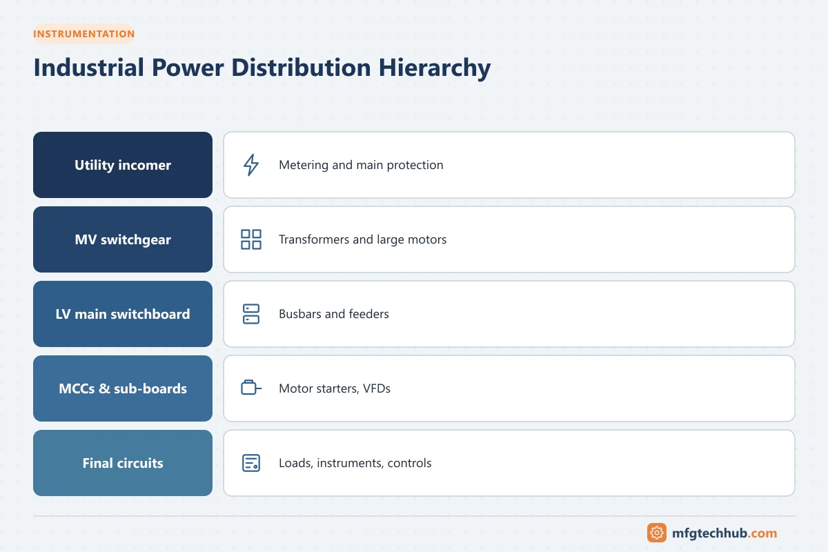
Typical industrial distribution hierarchy
Utility supply (HV/MV)
   └─ MV switchgear (e.g. 33 kV / 11 kV / 6.6 kV)
        └─ Transformers (MV/LV)
             └─ LV main switchboard / Power Control Centre (PCC)
                  ├─ Motor Control Centres (MCCs)
                  ├─ Power distribution boards (PDBs)
                  │    └─ Lighting and small power boards
                  └─ UPS and critical supplies
Voltages vary by country and utility; for example, 415/400 V three-phase in many IEC countries and 480 V in North America at low voltage.
Switchgear
Switchgear is the combination of switching devices (circuit breakers, switches, fuses), protection relays, measuring devices and busbars in an enclosure.
Medium-voltage switchgear
Used from about 1 kV to 36 kV and above (IEC 62271 series):
- Air-insulated switchgear (AIS): metal-enclosed panels with withdrawable vacuum circuit breakers
- Gas-insulated switchgear (GIS): compact, sealed designs using SF₆ or newer alternative gases
- Ring main units (RMUs): compact units used in secondary distribution networks
Each panel typically contains a circuit breaker, protection relay, current and voltage transformers, earthing switch, interlocks and metering.
Low-voltage switchgear and controlgear assemblies
Governed by IEC 61439, which defines design verification, temperature rise, short-circuit withstand and dielectric properties. Types include:
- Power Control Centres (PCC) / main LV switchboards: incomers (often ACBs), bus couplers and outgoing feeders
- Motor Control Centres (MCC): starters for motors, including DOL starters, star-delta starters, soft starters and VFD feeders, often in withdrawable modules
- Power and lighting distribution boards
Forms of internal separation
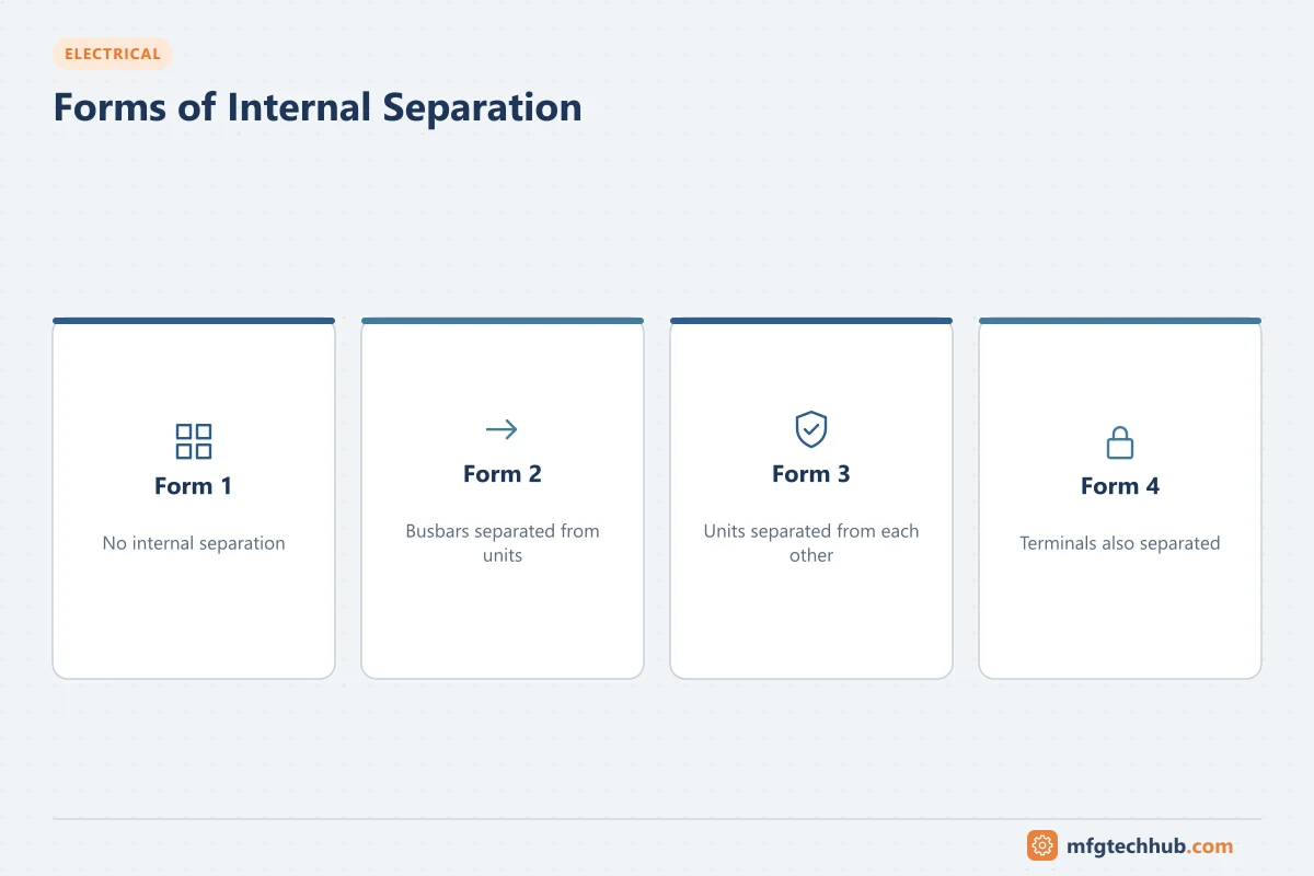
IEC 61439-2 defines forms of separation that divide an assembly into compartments, improving safety and allowing work on one circuit while others stay live:
| Form | Separation |
|---|---|
| Form 1 | No internal separation |
| Form 2 | Busbars separated from functional units |
| Form 3 | Busbars separated from functional units, and functional units separated from each other |
| Form 4 | As Form 3, plus terminals separated from each other |
Higher forms increase safety and availability but also cost and size. Form 4 is common for critical MCCs.
Busbars and busways
Busbars are rigid copper or aluminium conductors that distribute current within switchgear. Design considerations include:
- Current rating and temperature rise (cross-section, arrangement, ventilation)
- Short-circuit withstand: busbars and supports must withstand the mechanical forces and heating of the prospective fault current
- Insulation and clearances
Busways (bus ducts) carry large currents between transformers and switchboards, or along production lines with plug-in tap-off units. They are compact alternatives to multiple large cables and make it easier to relocate loads.
Protection and safety features
- Mechanical interlocks prevent opening doors on live compartments or closing earthing switches onto live circuits
- Padlocking facilities for lockout/tagout
- Arc fault containment: switchgear tested for internal arc classification (IAC under IEC 62271-200 for MV, and arc-resistant testing to IEC TR 61641 for LV) directs arc gases away from operators
- Remote racking and operation to keep people away during switching
- Degree of protection (IP rating) such as IP42 or IP54 for dust and water ingress
Integration with control systems
Modern switchgear includes intelligent devices:
- Protection relays and motor management relays communicating over IEC 61850, Modbus or PROFIBUS/PROFINET
- Digital meters for energy monitoring
- MCC modules with status, trip and current data available to the DCS or PLC
- Condition monitoring sensors (temperature of busbar joints, partial discharge in MV switchgear)
This allows operators to see breaker positions, alarms and energy data centrally. See Digital Power Meters and Energy Monitoring.
Maintenance
| Task | Purpose |
|---|---|
| Infrared thermography under load | Find hot joints and connections |
| Torque checks of busbar and cable connections | Prevent overheating |
| Breaker servicing and timing tests | Ensure correct operation |
| Protection relay testing | Verify settings and trip circuits |
| Insulation resistance testing | Detect insulation deterioration |
| Partial discharge testing (MV) | Detect insulation defects before failure |
| Cleaning and inspection | Remove dust and moisture, check for signs of tracking |
Always follow safe isolation procedures, arc flash rules and permit-to-work systems.
Key takeaways
- Industrial power flows from MV switchgear through transformers to LV switchboards, MCCs and distribution boards.
- IEC 62271 covers MV switchgear; IEC 61439 covers LV assemblies and forms of separation.
- Busbars must be sized for continuous current and short-circuit forces.
- Interlocks, arc containment and remote operation protect people; digital devices connect switchgear to plant systems.
Related tutorials
Before you apply this in a plant: this article is for education. Always check the current edition of the relevant standards, the manufacturer's documentation for your exact product and version, and your site's procedures. Safety-related work needs qualified personnel. See our editorial policy.