
Instrument Troubleshooting and Fault Diagnosis: A Practical Method
On this page
When an operator reports “the level reading is wrong,” the cause could be the process, the sensor, the transmitter, the wiring, the control system configuration or even the operator’s expectation. Good troubleshooters do not guess and replace parts. They follow a systematic method that quickly narrows the problem down, fixes the real cause, and does it safely.
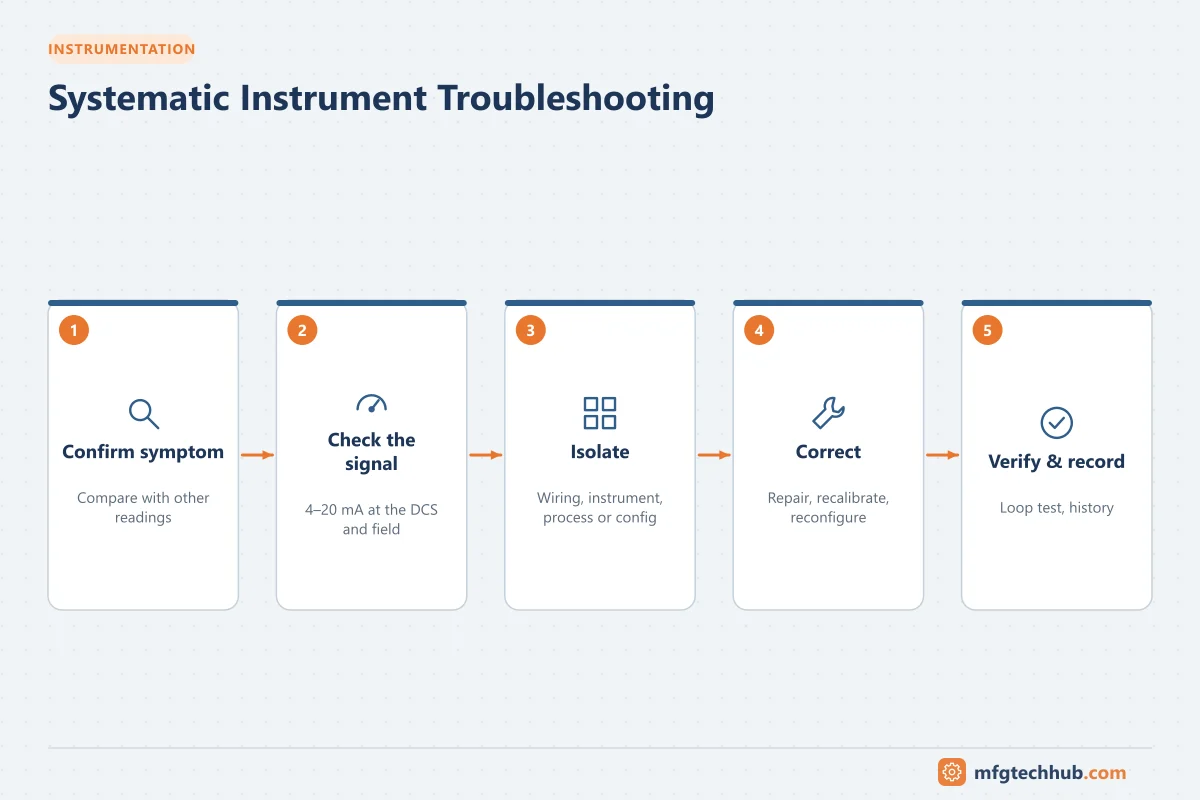
A systematic troubleshooting method
1. Gather information
- What exactly is the symptom? Reading too high, too low, frozen, noisy, drifting, or failed (for example at 0% or below)?
- When did it start? After maintenance, a process change, weather, a power event?
- Does the reading agree with other information, such as local gauges, related instruments, lab results or process behavior?
- What do the trends in the DCS or historian show?
Tip: trends are the most powerful diagnostic tool. A sudden step suggests a failure or change; a slow ramp suggests drift, build-up or blockage; a flat line suggests a frozen signal or saturated input.
2. Is it the process or the instrument?
Many “instrument problems” are real process conditions. Before touching the instrument, compare with:
- A local gauge or sight glass
- Redundant or related measurements (for example, inlet and outlet flows, pressure upstream and downstream)
- Mass and energy balance logic
3. Divide the loop (half-splitting)
Split the loop into sections and test at the midpoint to see which half contains the fault:
Process → Sensor → Transmitter → Field wiring → Barrier/isolator → I/O card → Configuration → HMIFor example, measure the current at the marshalling cabinet:
- If the current is correct for the process value, the fault is downstream (I/O card, scaling or display).
- If the current is wrong, the fault is upstream (transmitter, sensor, wiring or process connection).
4. Check signals with the right tools
- Loop calibrator or multimeter to measure current (in series) or voltage across a known resistor
- HART communicator to read the transmitter’s primary variable, output current, status and diagnostics
- Process calibrator to simulate sensor inputs
- Insulation tester for wiring faults
See Loop Calibrators for Process Control.
5. Fix the root cause
Replacing a transmitter that failed because of water ingress through a damaged gland only fixes the problem until the next failure. Identify and correct the underlying cause.
6. Verify and document
Confirm the reading is correct against a reference, return the loop to normal operation, inform operations, and record the fault, cause and action in the maintenance system.
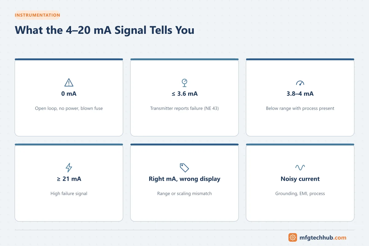
Interpreting 4-20 mA symptoms
| Measured current | Possible cause |
|---|---|
| 0 mA | Open circuit, blown fuse, no loop power, failed transmitter |
| About 3.6 mA or lower | Transmitter reporting a failure (NAMUR NE 43 downscale) |
| 3.8-4 mA with process present | Transmitter under-range, wrong range, blocked impulse line |
| Over 20.5 mA / 21 mA or higher | Over-range, or transmitter reporting a failure (upscale) |
| Correct current, wrong display | Wrong scaling in the DCS/PLC, wrong units, wrong I/O channel |
| Noisy current | Electrical noise, ground loops, vibration, process turbulence |
Use the 4-20 mA calculator to confirm the expected current for a given process value.
Common faults by measurement type
Pressure and differential pressure
- Blocked, leaking or frozen impulse lines
- Closed or partially open isolation or equalizing valves on manifolds
- Gas trapped in liquid lines, or liquid in gas lines
- Wrong zero after installation (mounting position, head of liquid)
- Diaphragm damage from overpressure
Level
- Changes in process density (DP, displacer)
- Wet-leg loss or evaporation
- Build-up on sensors (radar antennas, capacitance probes, displacers)
- Foam, turbulence or false echoes (radar and ultrasonic)
- Wrong tank geometry or range configuration
See the DP level calculator and Float, Displacer and DP Level Measurement.
Flow
- Partially full pipes or air entrainment (magnetic and ultrasonic meters)
- Insufficient straight pipe runs
- Orifice plate damage, wear or reversed installation
- Square-root extraction applied twice or not at all
- Low conductivity liquids on magnetic meters
- Coating on electrodes or sensors
Temperature
- Thermocouple type mismatch or wrong extension cable
- Reversed thermocouple polarity
- Missing or wrong cold junction compensation
- RTD lead resistance on 2-wire connections
- Thermowell not deep enough, or poor contact in the thermowell
See the RTD calculator to check resistance values.
Control valves
- Sticking (stiction), leading to oscillation
- Air supply problems
- Positioner calibration or feedback linkage errors
- Wrong fail-safe action
Safety during troubleshooting
- Always follow permit-to-work, isolation and lockout/tagout procedures.
- Understand the effect of your work on control and safety systems; put loops in manual or bypass trips only with authorization.
- Use intrinsically safe equipment in hazardous areas.
- Beware of process pressure, temperature and hazardous fluids when opening instrument connections.
- Remove all temporary bypasses, forces and jumpers when finished.
Key takeaways
- Start with information and trends, and decide whether the problem is the process or the instrument.
- Use half-splitting to locate the faulty section of a loop quickly.
- Know the typical faults of each measurement type.
- Fix root causes, verify the result and document the repair.
Related tutorials
Before you apply this in a plant: this article is for education. Always check the current edition of the relevant standards, the manufacturer's documentation for your exact product and version, and your site's procedures. Safety-related work needs qualified personnel. See our editorial policy.