
Ground Fault Detection and Maintenance in Industrial Systems
On this page
A ground fault (earth fault) occurs when a live conductor makes unintended contact with earth or grounded metalwork, usually because insulation has failed. Ground faults are the most common type of electrical fault. Depending on the system design, they may trip protection immediately, or they may persist silently until a second fault causes a much more serious failure. Detecting and fixing them quickly is essential for safety and reliability.
Why ground faults happen
- Insulation ageing, heat and moisture
- Mechanical damage to cables during construction or maintenance
- Contamination such as dust, oil or conductive deposits
- Water ingress in motors, junction boxes and cable glands
- Rodent damage and chafing
How system grounding affects detection
| System | First ground fault | Detection method |
|---|---|---|
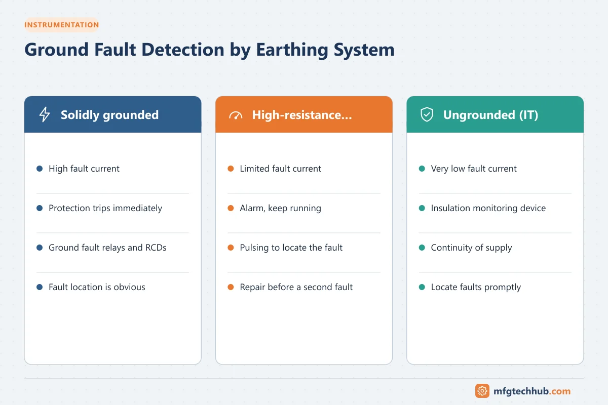
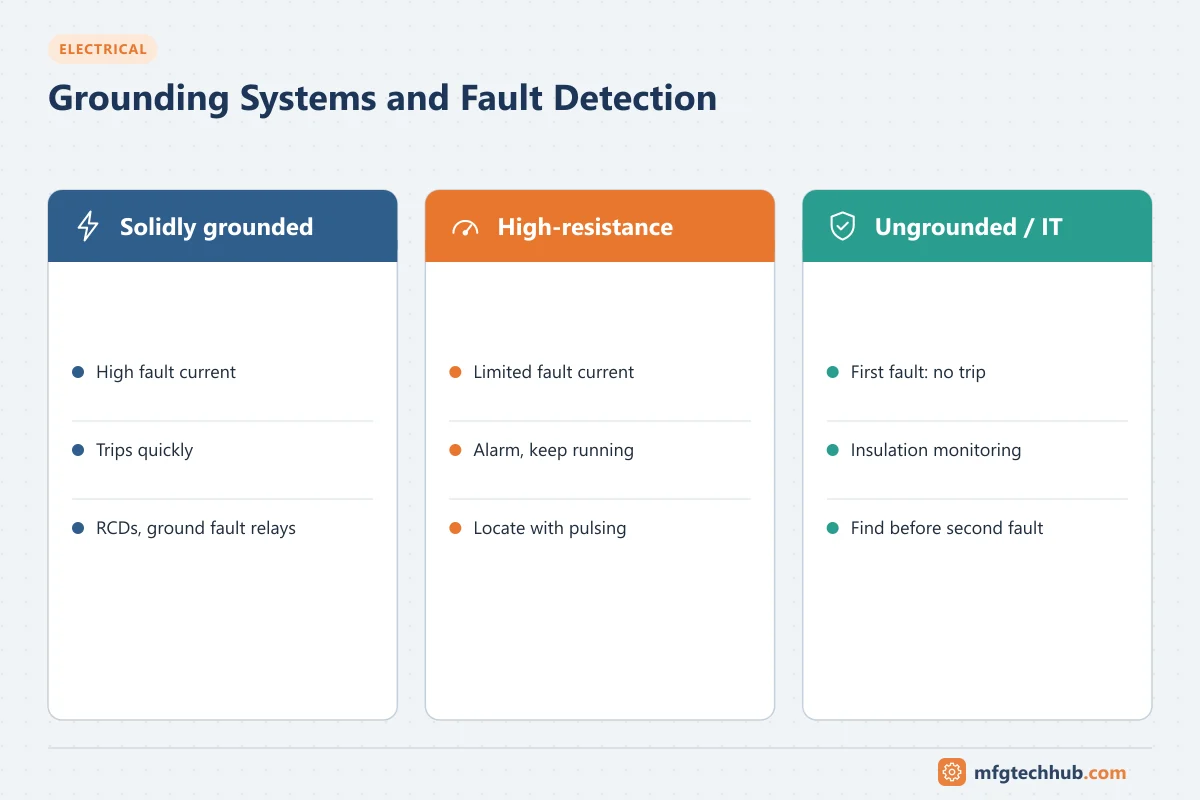
| Solidly grounded (TN) | High fault current; protection trips quickly | Overcurrent, ground fault relays, RCDs |
| High-resistance grounded (HRG) | Current limited (often to a few amperes); process keeps running | Alarm from the grounding resistor monitor; fault located and repaired while running |
| Ungrounded / IT system | Very small current; system keeps running | Insulation monitoring device (IMD) alarms |
High-resistance grounding is popular in continuous process plants because a single ground fault does not trip critical motors, avoiding unplanned shutdowns while limiting arc flash risk. However, a second ground fault on another phase creates a phase-to-phase fault through earth, so the first fault must be found and fixed promptly.
Ground fault protection in solidly grounded systems
- Residual current devices detect small leakage currents to protect people. See Earth Leakage Protection.
- Ground fault relays with core-balance (zero-sequence) CTs protect motors and feeders.
- Ground fault trip units on main breakers (the “G” in LSIG) protect against arcing ground faults that might not trip overcurrent settings.
Insulation monitoring in IT systems
An insulation monitoring device (IMD) injects a small measuring signal between the system and earth and continuously measures insulation resistance (IEC 61557-8). When resistance falls below a set threshold, it alarms. Insulation fault location systems (IEC 61557-9) inject a locating signal and use sensors on each outgoing circuit to identify the faulty feeder without shutting down.
IT systems are common in hospitals, marine installations, mines and some process plants, and in DC control and battery systems where ground faults can cause false operation of relays.
Locating ground faults in HRG systems
Many HRG systems include a pulsing feature that periodically changes the ground current. Technicians use a clamp-on ammeter to follow the pulsing current from the neutral grounding resistor, feeder by feeder, to the faulty circuit.
Insulation resistance testing
Insulation resistance testing (often called “meggering,” after an early instrument brand) applies a DC test voltage between conductors and earth and measures leakage resistance.
| Equipment voltage rating | Typical test voltage |
|---|---|
| Up to about 1,000 V AC | 500 V or 1,000 V DC |
| Medium-voltage equipment | 2,500 V or 5,000 V DC (per equipment standards) |
Polarization index (PI)
For motors, generators and transformers, the polarization index compares insulation resistance after 10 minutes to that after 1 minute:
PI = IR(10 min) ÷ IR(1 min)A rising resistance over time indicates clean, dry insulation; a low PI suggests moisture or contamination. IEEE 43 recommends a minimum PI of 2.0 for most modern insulation systems (Class B and higher) on rotating machines, together with minimum insulation resistance values.
Temperature matters: insulation resistance falls as temperature rises, so correct readings to a standard temperature when comparing results over time.
Safe testing practice
- Isolate and lock out the equipment; disconnect electronics such as drives, surge protectors and instruments that could be damaged.
- Discharge the equipment after testing; windings and cables store charge.
- Record results with temperature and humidity, and trend them.
Maintenance program for ground fault prevention
- Periodic insulation resistance tests on motors, cables and transformers
- Thermography to find overheating that damages insulation
- Inspection of cable glands, junction boxes and motor terminal boxes for water ingress
- Cleaning of motors and switchgear in dusty environments
- Testing of ground fault relays, RCDs and IMDs
- Prompt response to IMD and HRG alarms, with a defined time to locate and repair
Key takeaways
- Ground faults are the most common electrical fault and usually result from insulation deterioration.
- Solidly grounded systems trip quickly; HRG and IT systems keep running but must fix the first fault promptly.
- Insulation monitoring and fault location systems find faults without shutdown.
- Insulation resistance and polarization index tests reveal insulation condition before failure.
Related tutorials
Before you apply this in a plant: this article is for education. Always check the current edition of the relevant standards, the manufacturer's documentation for your exact product and version, and your site's procedures. Safety-related work needs qualified personnel. See our editorial policy.