
Functional Safety Explained: SIS, SIL, IEC 61508, IEC 61511 and the Safety Lifecycle
On this page
Functional safety is the part of overall safety that depends on a system or equipment operating correctly in response to its inputs. When a reactor’s pressure rises too high and an automated system closes the feed valve, that protection is a functional safety function. If it fails when needed, people can be hurt.
Important: this article is an educational introduction. Safety instrumented systems must be specified, designed, verified and maintained by competent people following the applicable standards (such as IEC 61511 or IEC 61508, or ISO 13849 / IEC 62061 for machinery), local regulations and your company’s procedures. Do not use this article as a design basis.
Key terms
| Term | Meaning |
|---|---|
| BPCS | Basic process control system: the normal control system (DCS/PLC) that keeps the process in its operating range |
| SIS | Safety instrumented system: sensors, logic solver and final elements that bring the process to a safe state when a hazard occurs |
| SIF | Safety instrumented function: one specific protective function, for example “close the feed valve on high reactor pressure” |
| SIL | Safety integrity level (1–4): the required risk reduction of a SIF |
| PFDavg | Average probability of failure on demand, used for low-demand SIFs |
| PFH | Average frequency of dangerous failure per hour, used for high-demand or continuous SIFs |
| Proof test | Periodic test to reveal dangerous failures not detected by diagnostics |
Which standard applies?
| Standard | Scope | Typical users |
|---|---|---|
| IEC 61508 | Generic functional safety standard for electrical/electronic/programmable safety-related systems | Manufacturers of safety devices (transmitters, safety PLCs, valves) and sectors without their own standard |
| IEC 61511 (ANSI/ISA-61511 in the US) | Safety instrumented systems for the process industry | Process plant owners, engineering contractors, integrators |
| ISO 13849 | Safety-related parts of machine control systems (performance levels PL a–e) | Machine builders |
| IEC 62061 | Functional safety of machinery control systems (SIL-based) | Machine builders |
Process plants use devices certified or proven-in-use to IEC 61508 principles within an IEC 61511 lifecycle.
SIL and risk reduction
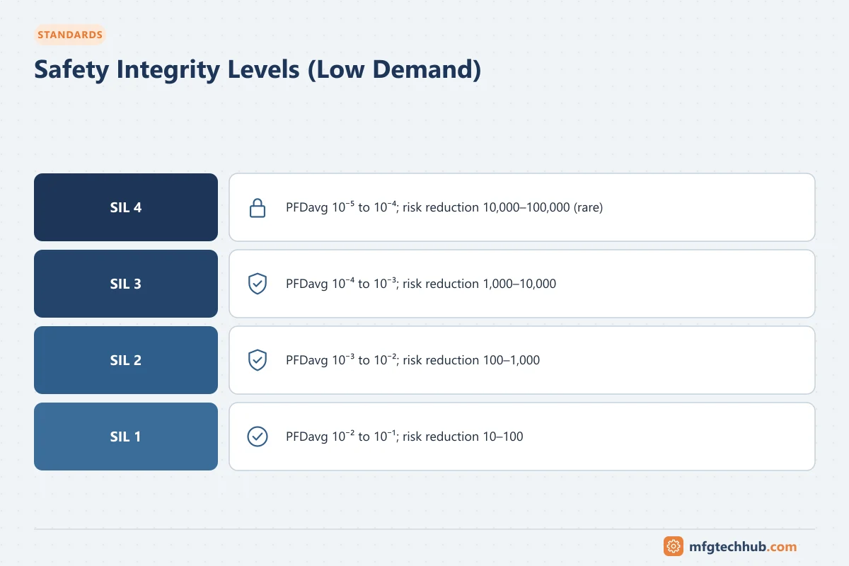
For low-demand safety functions (the most common case in process plants):
| SIL | PFDavg range | Risk reduction factor |
|---|---|---|
| SIL 1 | ≥ 0.01 to < 0.1 | 10 to 100 |
| SIL 2 | ≥ 0.001 to < 0.01 | 100 to 1,000 |
| SIL 3 | ≥ 0.0001 to < 0.001 | 1,000 to 10,000 |
| SIL 4 | ≥ 0.00001 to < 0.0001 | 10,000 to 100,000 |
SIL 4 is very rarely used in the process industry; designs requiring it are usually reconsidered to reduce risk by other means.
Achieving a SIL requires more than a PFD calculation. It also requires hardware fault tolerance (architectural constraints), systematic capability of the devices and software, and a compliant lifecycle and management system.
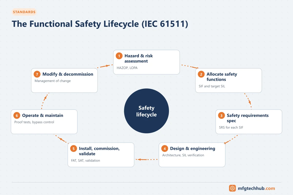
The safety lifecycle (IEC 61511 overview)
- Hazard and risk assessment, for example with HAZOP, to identify hazardous events and their consequences.
- Allocation of safety functions to protection layers, often using LOPA (layer of protection analysis): which independent layers (BPCS, alarms with operator response, relief valves, SIS) reduce the risk, and what SIL is needed for each SIF.
- Safety requirements specification (SRS): for each SIF, what it senses, what it does, the safe state, the SIL, response time, proof test interval, bypass and reset requirements.
- Design and engineering: device selection, architecture (voting), logic, SIL verification calculations.
- Installation, commissioning and validation: including a site acceptance test that proves every SIF works as specified.
- Operation and maintenance: proof testing, bypass management, recording demands and failures.
- Management of change: every modification assessed and re-verified.
- Decommissioning.
Functional safety assessments at defined stages and a functional safety management system (competence, procedures, audits) run across the whole lifecycle.
Protection layers: why the SIS must be independent
A plant uses several layers: process design, BPCS control, alarms and operator response, SIS, mechanical protection (relief valves, rupture discs), and emergency response. For the SIS to count as an independent layer, it must not share failure causes with the BPCS. Common independence measures:
- Separate sensors for SIF and control (or rigorously justified sharing)
- Separate logic solver (safety PLC)
- Separate final elements, or a dedicated trip solenoid on a shared valve with justification
- Controlled access to the safety system configuration
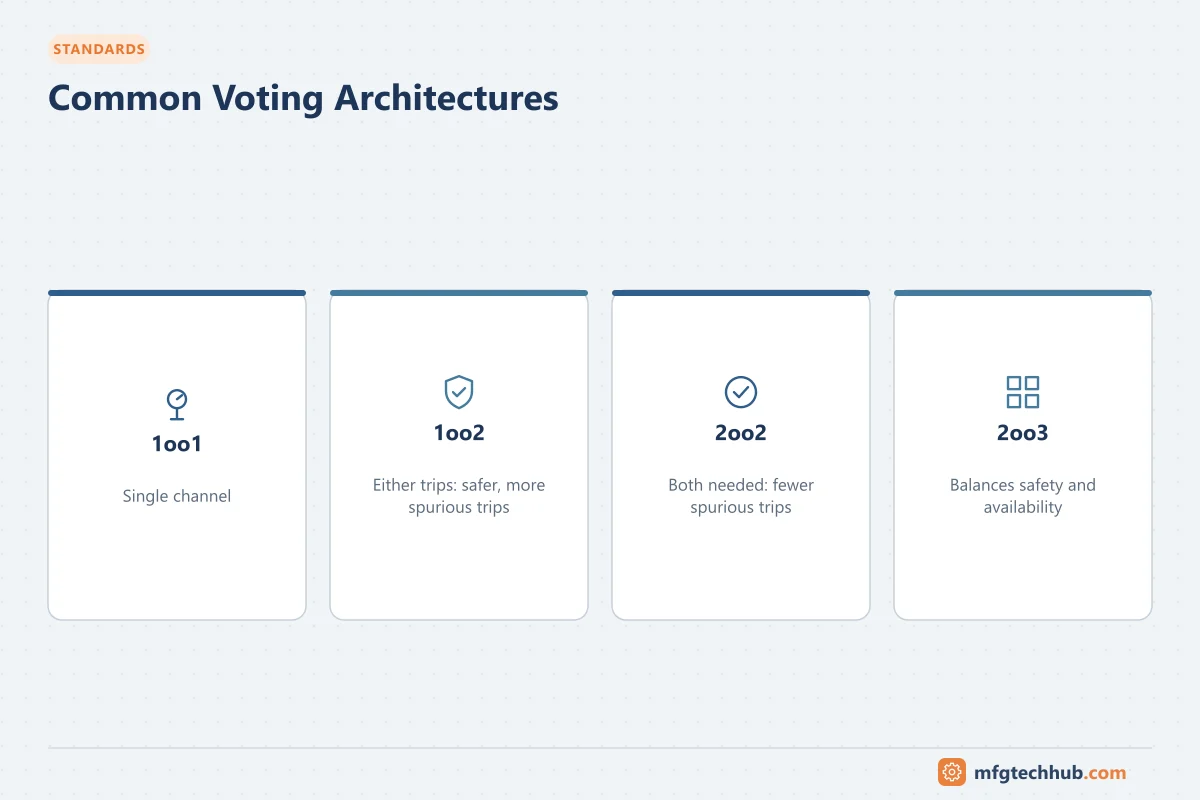
Voting architectures
| Architecture | Meaning | Characteristics |
|---|---|---|
| 1oo1 | One sensor; trips if it demands | Simple; a single failure can prevent a trip or cause a spurious trip |
| 1oo2 | Two sensors; trips if either demands | Higher safety; more spurious trips |
| 2oo2 | Trips only if both demand | Fewer spurious trips; lower safety |
| 2oo3 | Three sensors; trips if any two demand | Good balance of safety and availability; common for critical SIFs |
The same logic applies to logic solvers and final elements. Diagnostics (for example comparing redundant transmitters and alarming on deviation) improve both safety and availability.
Proof testing and diagnostics
- Diagnostics detect some failures automatically (for example a transmitter outside 4–20 mA, which the SIS must treat according to the SRS).
- Proof tests reveal dangerous undetected failures, such as a valve that will not close fully. The proof test interval assumed in the SIL calculation must actually be achieved in operation.
- Partial stroke testing can test valve movement between full proof tests.
- Proof test coverage matters: a test that does not exercise the full function (sensor to valve closure) leaves some failures undetected.
Bypasses, overrides and resets
Bypasses are necessary for maintenance and start-up, but they disable protection. Good practice:
- Formal authorisation and logging of every bypass
- Time limits and alarms for active bypasses
- Compensating measures while bypassed
- Manual reset after a trip, so equipment does not restart automatically without confirmation
Common weaknesses found in practice
- SIFs defined without a clear SRS, or the SRS not updated after changes
- Proof tests overdue or not covering the full function
- Bypasses left active
- Sensors shared with control without justification
- Final elements (valves) not selected, maintained or tested to the assumed performance
- Missing records of demands and failures, so the design assumptions cannot be verified
Machinery safety in brief
Machine builders usually apply ISO 12100 (risk assessment) and then design safety functions (emergency stop, guard interlocking, safe speed) to ISO 13849-1 (performance levels PL a–e) or IEC 62061 (SIL). Safety PLCs, safety relays, safe drives (safe torque off) and safety networks (for example PROFIsafe, CIP Safety, FSoE) are the typical building blocks. See PLC Application Examples for how standard logic and safety functions are kept separate.
Frequently asked questions
What is the difference between a BPCS and an SIS?
The BPCS controls the process during normal operation. The SIS is an independent system that acts only when a hazardous condition occurs, bringing the process to a safe state. They should not share components in a way that allows one failure to disable both.
Does a safety PLC make a function SIL-rated?
No. A certified safety PLC is only one part. The whole function (sensors, logic, final elements), its architecture, reliability data, proof testing, and the lifecycle management must meet the required SIL.
Who decides the SIL of a safety function?
The SIL target comes from the hazard and risk assessment (for example HAZOP and LOPA) carried out by a multidisciplinary team, including process, operations, safety and instrumentation specialists.
Key takeaways
- Functional safety concerns protective functions that must work on demand.
- IEC 61508 is the generic standard; IEC 61511 applies to process-industry SIS; ISO 13849 and IEC 62061 apply to machinery.
- SIL defines the required risk reduction and requires hardware, systematic and lifecycle compliance.
- Independence, proof testing, bypass control and management of change keep an SIS effective over its life.
Before you apply this in a plant: this article is for education. Always check the current edition of the relevant standards, the manufacturer's documentation for your exact product and version, and your site's procedures. Safety-related work needs qualified personnel. See our editorial policy.