
PLC Interview Questions and Answers
On this page
These questions come up regularly in interviews for automation, controls and instrumentation roles. The answers are short and practical; each links to a full tutorial if you want to go deeper. Interviewers care less about textbook definitions than about whether you understand how things behave in a real plant, so try to add an example from your own experience to each answer.
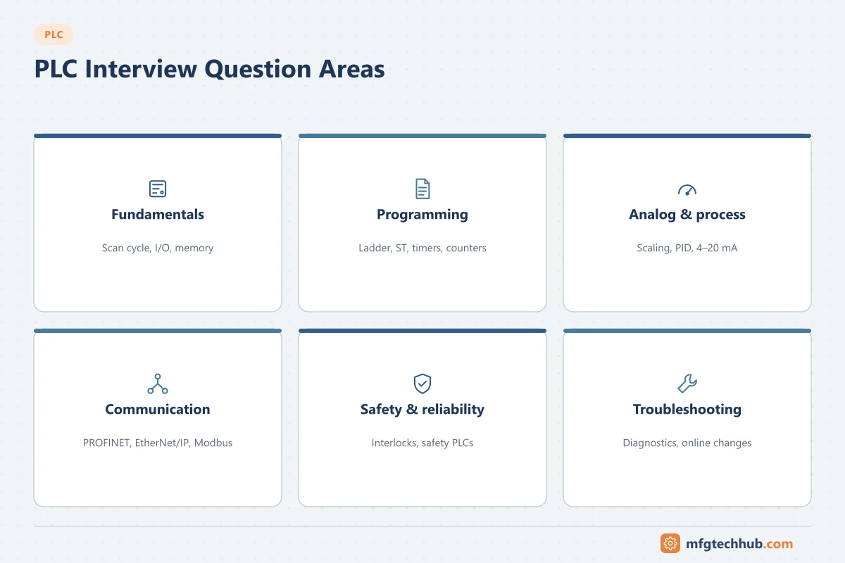
Fundamentals
1. What is a PLC?
A Programmable Logic Controller is a ruggedized industrial computer that reads inputs from sensors and switches, executes a user program, and controls outputs such as motors, valves and indicators in real time. PLCs replaced hard-wired relay panels because logic can be changed in software. Read more in What Is a PLC?
2. What are the main components of a PLC?
The power supply, the CPU (processor and memory), input and output modules, communication interfaces, and a programming device or software. Modular PLCs mount these on a rack or DIN rail. See PLC components.
3. Explain the PLC scan cycle.
The PLC repeatedly: (1) reads all inputs into an input image table, (2) executes the program from top to bottom using that image, (3) writes results to the output image and physical outputs, and (4) performs communication and housekeeping. The time for one cycle is the scan time, typically a few milliseconds. See How PLCs Work.
4. Why does scan time matter?
Any input that changes and changes back within one scan may be missed, and outputs are only updated once per scan. Long scan times make fast processes hard to control. High-speed events are handled with interrupts, high-speed counter modules, or by running critical logic in a faster cyclic task.
5. What is the difference between sinking and sourcing I/O?
A sourcing device supplies current (it connects the load to +V); a sinking device provides the path to 0 V (common). A sourcing sensor must connect to a sinking input and vice versa. In Europe, PNP (sourcing) sensors are most common; NPN (sinking) sensors are common in parts of Asia.
6. What types of PLCs are there?
Compact (fixed I/O), modular (rack or backplane based), and PLCs integrated into other devices. Safety PLCs are certified for safety functions. See Types of PLCs.
7. PLC vs DCS: what is the difference?
PLCs grew from machine and discrete control and excel at fast logic. DCS grew from continuous process control and emphasize integrated engineering, a common database, operator displays and plant-wide control. The boundary has blurred, but DCS remain dominant in large process plants. See What Is a DCS?
Programming
8. Which programming languages does IEC 61131-3 define?
Ladder Diagram (LD), Function Block Diagram (FBD), Structured Text (ST), Sequential Function Chart (SFC), and Instruction List (IL), which is deprecated in the current edition. See PLC programming languages.
9. What is the difference between a normally open and a normally closed contact in ladder logic?
An examine-if-closed (normally open) contact is true when its bit is 1. An examine-if-open (normally closed) contact is true when its bit is 0. The ladder symbol describes the logic test, not the wiring of the physical device. For example, a stop button is usually wired normally closed for fail-safety, so in the program you examine it as closed (true when the button is not pressed).
10. How do you write a start/stop (seal-in or latching) circuit?
The start button in parallel with a contact of the motor output, both in series with the stop condition, driving the motor output. When start is pressed, the output turns on and “seals in” through its own contact until the stop condition breaks the rung.
11. What are the common timer types?
- TON (on-delay): output turns on after the input has been true for the preset time.
- TOF (off-delay): output stays on for the preset time after the input goes false.
- TP / RTO: pulse timers, and retentive timers that keep accumulated time when the input goes false.
12. How do counters work?
Up counters (CTU) increment on each false-to-true transition of the input; down counters (CTD) decrement. The done bit sets when the accumulated value reaches the preset. A reset instruction clears the count.
13. What is a one-shot (edge detection)?
An instruction that is true for exactly one scan when its input changes from false to true (rising edge) or true to false (falling edge). It is used so actions such as counting or moving data happen once per event rather than every scan.
14. What is the difference between a latch/set and a normal output coil?
A normal coil follows the rung condition each scan. A latch (set) coil turns the bit on and keeps it on until an unlatch (reset) instruction clears it, even if the rung goes false. Latched bits often retain their state through a power cycle, so they must be used carefully.
15. How do you scale an analog input?
Convert the raw count to engineering units with a linear equation: EU = (raw − raw_min) × (EU_max − EU_min) ÷ (raw_max − raw_min) + EU_min. Many platforms provide a scaling block. The 4-20 mA calculator shows the same relationship for current signals.
16. What makes a PLC program easy to maintain?
Consistent tag naming, modular structure (routines or function blocks per equipment), comments, avoiding duplicate output coils, standard templates for motors and valves, and version control. See PLC programming best practices.
17. Why should you avoid writing to the same output in two places?
Because the last rung executed wins, which makes behavior depend on program order and makes troubleshooting confusing. Combine the conditions into one rung or use intermediate bits.
Analog and process control
18. What is a 4-20 mA signal, and why not 0-20 mA?
A current signal proportional to the measurement. The 4 mA “live zero” distinguishes a genuine zero from a broken wire (0 mA) and powers two-wire transmitters.
19. What is PID control?
A feedback algorithm combining proportional, integral and derivative actions to hold a process variable at its setpoint. See PID Control Explained.
20. What is the difference between a two-wire and a four-wire transmitter?
A two-wire (loop-powered) transmitter takes its power from the 4-20 mA loop itself. A four-wire transmitter has separate power supply wiring and signal wiring.
Communication
21. Which industrial protocols have you used?
Be ready to discuss at least one fieldbus or industrial Ethernet protocol (PROFINET, EtherNet/IP, Modbus) and one integration protocol (OPC UA). See industrial communication protocols.
22. What is the difference between Modbus RTU and Modbus TCP?
Both use the same data model (coils, discrete inputs, holding and input registers). RTU runs over serial links such as RS-485; TCP runs over Ethernet on port 502.
23. How does a PLC communicate with SCADA?
Typically through a driver or OPC server that polls PLC tags over an industrial protocol, or through a native protocol supported by the SCADA software. See RTUs and PLCs in SCADA.
Safety and reliability
24. Why are stop buttons wired normally closed?
So that a broken wire or loss of power has the same effect as pressing stop. This is a fail-safe design principle.
25. What is a safety PLC?
A PLC certified to IEC 61508 for safety functions, with redundant processing, diagnostics and restricted programming. It is used for emergency stops, burner management and machine guarding. Standard PLC logic should never be relied on for life safety.
26. What is redundancy in PLC systems?
Duplicated CPUs, power supplies or networks so the system keeps running if one component fails. Hot-standby CPUs switch over without stopping the process.
27. How do you protect a PLC from cyber threats?
Network segmentation, firewalls, disabling unused services, strong passwords, keeping firmware updated, controlling programming access (key switch or run mode), and following IEC 62443. See PLC security concerns.
Troubleshooting
28. A motor does not start when commanded. How do you troubleshoot?
Work from the program to the field: check the output bit is on in the program, check the output module LED, measure voltage at the output terminal, then check the contactor coil, overloads, interlocks, and motor power. At each step, confirm the permissive and interlock conditions in the logic. See the PLC troubleshooting guide.
29. An analog value reads full scale. What could be wrong?
Common causes: an open circuit on a voltage input, over-range on a current input, wrong input type configuration (voltage vs current), a failed transmitter driving high (NAMUR NE 43 failure current), or a wiring short.
30. The PLC faulted and stopped. What do you do first?
Record the fault code and diagnostic buffer before clearing anything. Common causes include math errors, array index out of range, watchdog (scan time) timeouts, module failures and power problems. Fix the cause, then return to run mode following site procedures.
31. How do you make a change to a running PLC safely?
Follow change management: get approval, back up the current program, understand the effect on the running process, use online editing features carefully, test the change, and document it. Never force I/O without authorization and a clear plan to remove the force.
Behavioral and project questions
32. Describe a project you commissioned.
Structure your answer: the system and its purpose, your role, a specific technical challenge, what you did, and the result. Mention loop checks, FAT/SAT, documentation and teamwork. See PLC project process.
33. How do you keep your skills current?
Mention vendor training, standards (IEC 61131-3, IEC 62443), practice with simulators, and following industry resources. Our automation engineer roadmap lists what to learn next.
Interview tips
- Draw simple sketches: a ladder rung, a loop diagram, a network layout.
- Be honest about what you do not know, and explain how you would find out.
- Show a safety-first mindset: interlocks, permits, lockout/tagout and change control.
- Relate answers to real examples from projects, internships or training rigs.