
PLC Project Process and Best Practices: From Requirements to Commissioning and Support
On this page
A PLC project turns a machine or process requirement into a tested, documented control system that operators can run and maintenance can support. The phases are similar whether the scope is a single packaging machine, a production line or a process skid. Most project trouble comes not from programming but from unclear requirements, late changes, incomplete testing and missing documentation, so this guide focuses on the deliverables and practices that prevent them.
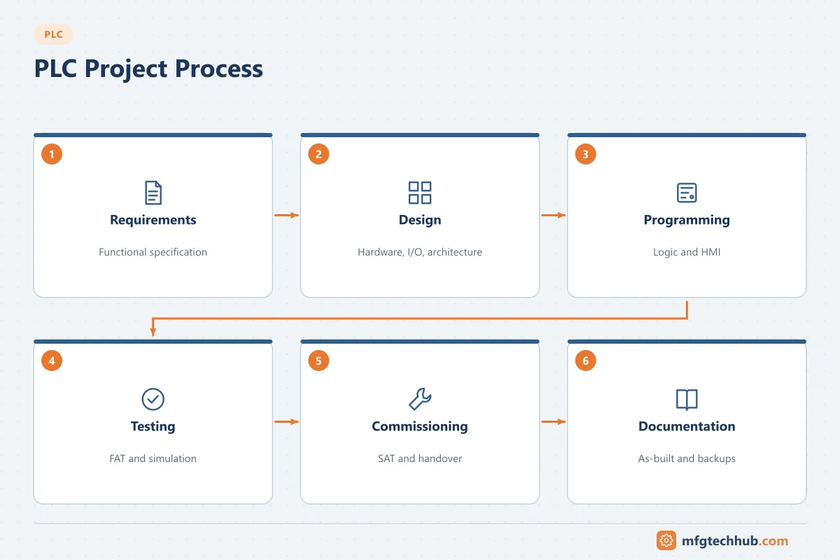
For plant-wide and multi-site projects, see DCS Project Lifecycle and SCADA Project Process.
Phase 1: Requirements
- Capture what the machine or process must do: products, speeds, modes (automatic, manual, maintenance), recipes, interfaces and operator tasks.
- Agree the standards to follow: customer automation standards, preferred PLC platform, naming conventions, HMI style, network and security rules.
- Identify interfaces to upstream and downstream machines, MES or SCADA.
Deliverable: user requirements specification (URS).
Phase 2: Risk assessment and safety
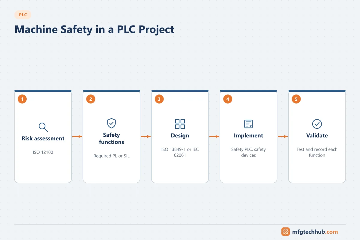
For machinery, a risk assessment (ISO 12100 gives the general principles) identifies hazards and required risk reduction. Safety functions such as emergency stop, guard interlocking and safe speed are then specified with required performance levels (ISO 13849-1) or SIL (IEC 62061). In process skids, safety instrumented functions follow IEC 61511. In the EU, machinery must meet the Machinery Directive, which is being replaced by the Machinery Regulation (EU) 2023/1230, applicable from 20 January 2027.
Deliverables: risk assessment, safety requirements specification, safety function list. See PLC Industry Standards and Functional Safety.
Phase 3: Functional design
- Functional design specification (FDS): sequences, modes, interlocks, alarms, recipes, HMI screens and communication, described so that the customer can approve them and the tester can test them.
- I/O list: every signal with tag, description, type, range, module and channel.
- Alarm list with priorities and operator responses.
- Network architecture and IP addressing, including security zones. See OT Network Design Fundamentals.
Phase 4: Hardware and electrical design
- Select the PLC platform, I/O and safety components with spare capacity for changes. See PLC Components and Types of PLCs.
- Electrical schematics, panel layout, cable lists, power supply sizing, grounding and EMC design.
- Panel standards such as IEC 60204-1 (electrical equipment of machines) and, where relevant, UL 508A in North America.
Phase 5: Programming and HMI
- Program according to the agreed standard: structure by equipment, reusable function blocks, state machines for sequences. See PLC Programming Best Practices.
- Build HMI screens from templates following the HMI style guide.
- Keep a change log from the first day and archive versions.
Phase 6: Testing before site
| Test | What it covers |
|---|---|
| Internal test / simulation | Logic tested against the FDS with simulated I/O or a machine model |
| Panel test | Wiring, power, I/O channels, network communication |
| Factory acceptance test (FAT) | Customer witnesses operation against the FDS: modes, sequences, interlocks, alarms, faults, recipes |
| Safety function validation | Each safety function tested and documented |
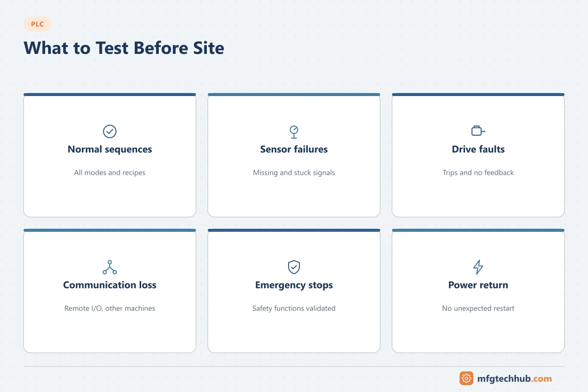
Test failure scenarios, not only the normal sequence: sensor failures, drive faults, communication loss, emergency stops and power return. See PLC Programming Software and Tools for simulation.
Phase 7: Installation, SAT and commissioning
- Installation checks: mechanical, electrical, grounding, cable terminations.
- I/O checks: every input and output from device to PLC and HMI.
- Motor direction, drive parameters, valve operation.
- Functional tests with the machine dry, then with product.
- Site acceptance test (SAT) against agreed criteria.
- Performance run where the contract requires it.
Remove all forces and debug code before handover, and back up the final program.
Phase 8: Handover and support
Handover package:
- As-built electrical drawings, I/O list and network documentation
- Final PLC and HMI programs (archived, with version and change log)
- FDS updated to match the final system
- Safety validation records
- Operating and maintenance manuals, spare parts list
- Training records
- Backup and restore procedure
After start-up: management of change, periodic backups and comparisons, firmware and security updates, and a lifecycle plan for obsolete components. See PLC Upgrading and Integration Challenges and PLC Security.
Best practices by phase
| Phase | Best practices |
|---|---|
| Requirements | Get operators and maintenance involved early; agree standards before design |
| Safety | Do the risk assessment before hardware design; specify safety functions with required PL or SIL |
| Design | Write an FDS the customer can approve and the tester can test; freeze the I/O list with change control |
| Hardware | Leave spare I/O, slots and power; separate field and CPU power supplies |
| Programming | Use company standards and tested function blocks; review code |
| Testing | Simulate before FAT; test fault paths; record every test result |
| Commissioning | Check every I/O point; remove forces; back up the final program |
| Support | Keep documents as-built; manage changes and backups; plan for obsolescence |
| Security | Change default passwords, restrict remote access, harden engineering laptops |
Common pitfalls
| Pitfall | Effect | Prevention |
|---|---|---|
| Programming starts before the FDS is agreed | Rework and disputes | Approve the FDS first, or at least the typicals |
| Late I/O changes without control | Wiring and program errors | I/O freeze date and change control |
| FAT tests only the normal sequence | Faults discovered on site | Test plans that include failure cases |
| Site changes not reflected in documents | Next change based on wrong drawings | As-built updates as a handover condition |
| No backup of the final program | Long recovery after a failure | Archive at handover and after every change |
| Safety functions tested informally | Unproven safety, legal risk | Formal validation with records |
Frequently asked questions
What are the main phases of a PLC project?
Requirements, risk assessment, functional design, hardware design, programming, testing (simulation and FAT), installation and commissioning with SAT, and handover with long-term support.
What documents are needed for a PLC project?
At minimum a requirements specification, risk assessment, functional design specification, I/O list, electrical drawings, network documentation, test records, final programs with change log, and operating and maintenance documentation.
What is the difference between FAT and SAT?
The factory acceptance test checks the system against the specification before shipment, often with simulated process conditions. The site acceptance test checks it on site with the real machine or process.
Key takeaways
- Agree requirements, standards and the FDS before programming.
- Do the risk assessment early and validate safety functions formally.
- Simulate and test failure cases before FAT; check every I/O point on site.
- Hand over as-built documents, archived programs and a support plan.
Related tutorials
Before you apply this in a plant: this article is for education. Always check the current edition of the relevant standards, the manufacturer's documentation for your exact product and version, and your site's procedures. Safety-related work needs qualified personnel. See our editorial policy.