
Servo Motion Control Explained: Servo Motors, Encoders, Drives, Sizing, Tuning and PLCopen Motion
On this page
Packaging machines, pick-and-place systems, printing presses, cutting machines and robot axes all rely on servo motion control: moving a load to a precise position, at a controlled speed, often synchronised with other axes. This article explains how servo systems work, how to size and tune them, and how PLCs command them.

For motor basics see Types of Industrial Motors; for variable-speed drives without position control see VFDs and Soft Starters.
Servo system components
| Component | Role |
|---|---|
| Motion controller | Generates motion profiles (position, velocity, acceleration over time); may be a PLC with motion functions, a dedicated motion controller or part of the drive |
| Servo drive (amplifier) | Closes the control loops and supplies current to the motor |
| Servo motor | Usually a permanent-magnet synchronous motor with low inertia and high dynamic torque |
| Feedback device | Encoder or resolver measuring position (and speed) |
| Mechanics | Gearboxes, belts, ball screws, rack and pinion, couplings, and the load itself |
The cascaded control loops
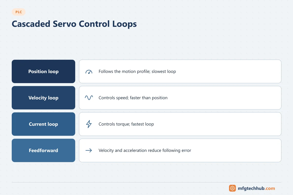
Servo drives typically use three nested loops:
| Loop | Controls | Typical update rate |
|---|---|---|
| Current (torque) loop | Motor current, hence torque | Fastest (tens of kHz range in many drives) |
| Velocity loop | Speed | Faster than position loop |
| Position loop | Position following the motion profile | Slowest of the three |
Feedforward (velocity and acceleration feedforward) lets the drive anticipate the motion profile instead of waiting for errors, greatly reducing following error (the difference between commanded and actual position).
Feedback devices
| Type | Description | Notes |
|---|---|---|
| Incremental encoder | A/B quadrature pulses plus index (Z) | Needs homing after power-up |
| Absolute encoder (single-turn / multi-turn) | Reports absolute position; multi-turn keeps count across revolutions | Avoids homing after power loss; uses serial interfaces (for example SSI, EnDat, BiSS, or vendor protocols) |
| Resolver | Analog rotary transformer | Robust in harsh environments; lower resolution |
Motion networks
Multi-axis motion needs deterministic, synchronised communication between controller and drives. Common networks include EtherCAT, PROFINET IRT, SERCOS III and EtherNet/IP with CIP Motion. See PROFINET Explained and EtherNet/IP and CIP.
Sizing a servo axis
- Define the motion profile: distances, times, velocities, accelerations, dwell times, duty cycle.
- Calculate the load: mass or inertia, friction, gravity (vertical axes), process forces (cutting, pressing).
- Reflect load to the motor through the transmission (gear ratio, screw lead, pulley diameter).
- Calculate torques: peak torque during acceleration, and RMS torque over the cycle, which determines motor heating.
- Check speed against the motor’s maximum speed at the available voltage.
- Check the inertia ratio (load inertia reflected to the motor ÷ motor inertia). Lower ratios are easier to control; many suppliers recommend limits depending on stiffness and performance (a ratio below about 10:1 is a common guideline, lower for high dynamics).
- Select the drive for continuous and peak current, and consider regenerative energy (braking resistors or regenerative supplies) for frequent decelerations or vertical loads.
- Holding brakes for vertical axes and safety.
Manufacturer sizing software performs these calculations with real motor data; use it and add safety margins.
Tuning
- Start with the drive’s auto-tuning to identify inertia and set initial gains.
- Tune current, velocity and position loops in that order (inner to outer).
- Add feedforward to reduce following error.
- Use notch filters to suppress mechanical resonances (belts, long shafts, flexible frames).
- Verify with trace/scope functions in the drive: commanded vs actual position, following error, torque.
Mechanical problems (backlash, loose couplings, compliant structures) cannot be tuned away; fix the mechanics first.
Commanding motion from a PLC: PLCopen motion blocks
PLCopen defines standard motion function blocks for IEC 61131-3, supported (with variations) by many PLC and motion vendors:
| Function block | Purpose |
|---|---|
| MC_Power | Enable/disable the axis |
| MC_Reset | Reset axis errors |
| MC_Home | Perform homing |
| MC_MoveAbsolute / MC_MoveRelative | Move to a position or by a distance |
| MC_MoveVelocity | Run at a set velocity |
| MC_Stop / MC_Halt | Stop the axis (Stop is a controlled stop that blocks further motion until released; Halt is a normal stop) |
| MC_GearIn / MC_GearOut | Electronic gearing to a master axis |
| MC_CamIn / MC_CamOut | Electronic cam profiles relative to a master |
| MC_ReadStatus / MC_ReadActualPosition | Monitor axis state and position |
Axes follow a defined state machine (disabled, standstill, discrete motion, continuous motion, synchronised motion, stopping, error stop, homing). Good PLC code checks axis state and error outputs of every block. See PLC Programming Best Practices.
Homing
Homing establishes the reference position for incremental systems or after mechanical changes: moving to a home switch, using the encoder index pulse, a hard stop (with torque limit), or setting the current position. Absolute multi-turn encoders usually avoid homing after power loss.
Electronic gearing and cams
Instead of mechanical line shafts and cams, electronic gearing keeps a slave axis at a ratio to a master (for example a conveyor), and electronic cams define complex position relationships (for example a flying knife or rotary cutter synchronised to a web). Profiles can be changed per product without mechanical changes.
Drive-integrated safety functions
Modern servo drives include safety functions defined in IEC 61800-5-2, such as:
| Function | Meaning |
|---|---|
| STO (Safe Torque Off) | Removes torque-producing power from the motor |
| SS1 (Safe Stop 1) | Controlled stop, then STO |
| SS2 (Safe Stop 2) | Controlled stop, then safe operating stop with the drive still powered |
| SLS (Safely Limited Speed) | Monitors that speed stays below a limit, for example during manual intervention |
They are used within safety functions designed to ISO 13849-1 or IEC 62061. See Functional Safety and Industrial Robots.
Troubleshooting
| Symptom | Likely causes | Checks |
|---|---|---|
| Following error fault | Too high acceleration, insufficient torque, mechanical binding, poor tuning | Drive scope trace; torque vs limit; mechanics |
| Overcurrent / overload | Undersized motor or drive, jam, brake not released | Duty cycle, brake control, mechanical load |
| Encoder or feedback error | Cable damage, shield/grounding, connector problems | Cable routing, shield termination, connectors |
| Audible noise or vibration | Mechanical resonance, excessive gains | Notch filters, reduce gains, check couplings |
| Position drift | Slipping coupling or belt, lost home, incremental encoder noise | Mechanical checks, rehome, shielding |
| Overvoltage on deceleration | Regenerative energy not absorbed | Braking resistor sizing, deceleration ramps |
Frequently asked questions
What is the difference between a servo drive and a VFD?
A VFD mainly controls motor speed, often without position feedback. A servo drive controls torque, speed and position with high dynamics and precise feedback, for applications that need accurate positioning and synchronisation.
What is following error?
The difference between the commanded position and the actual position of an axis during motion. It is used to judge tuning quality and to detect faults when it exceeds a limit.
Why is the inertia ratio important?
A high ratio of load inertia to motor inertia makes the axis harder to control and more sensitive to mechanical compliance and resonance. Keeping it within supplier recommendations helps achieve stable, fast motion.
Key takeaways
- Servo drives use cascaded current, velocity and position loops with feedforward for accurate motion.
- Size axes from the motion profile: peak and RMS torque, speed, inertia ratio and regenerative energy.
- PLCopen motion blocks provide a standard way to command axes from a PLC; check axis states and errors.
- Drive safety functions such as STO, SS1 and SLS support machine safety designs.
Related tutorials
Before you apply this in a plant: this article is for education. Always check the current edition of the relevant standards, the manufacturer's documentation for your exact product and version, and your site's procedures. Safety-related work needs qualified personnel. See our editorial policy.