
How PLCs Work: The Scan Cycle, Process Image, Tasks, Response Time and Watchdog
On this page
A PLC does not react to inputs the way a relay circuit does, with every contact acting at the same moment. It works in a repeating cycle: take a snapshot of the inputs, execute the program from top to bottom, then write the results to the outputs. Understanding this cycle explains most “strange” PLC behaviour: a short pulse that is missed, an output that flickers, or a machine that responds a few milliseconds later than expected.
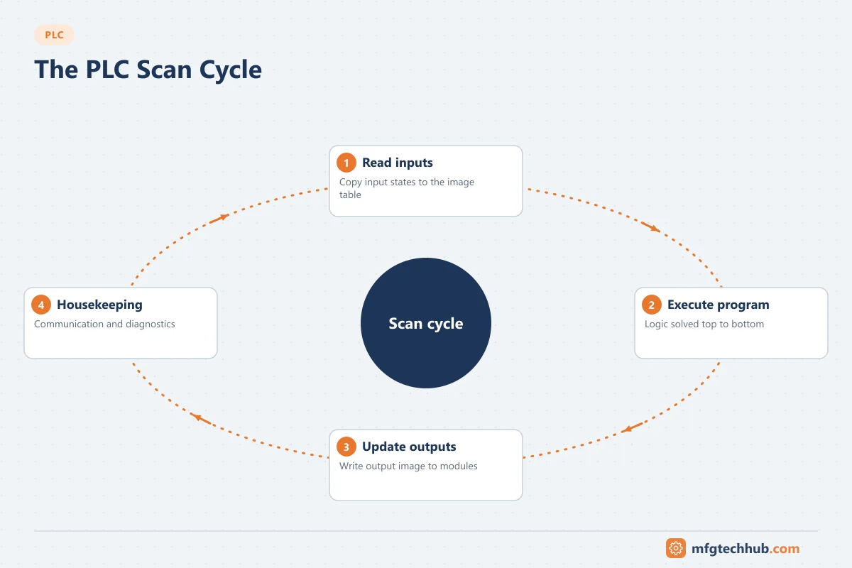
The classic scan cycle
| Phase | What happens |
|---|---|
| 1. Input scan | The states of all inputs are copied into the input process image (a memory table) |
| 2. Program execution | The program runs from top to bottom using the process image, not the live terminals; results are written to the output process image |
| 3. Output scan | The output process image is copied to the physical outputs |
| 4. Housekeeping | Communication with HMI and programming tools, diagnostics, self-tests |
Because the program works on a snapshot, every rung sees the same input values during one scan, even if a sensor changes halfway through. Outputs change only at the end of the scan, all together.
Scan time
Scan time is the time for one complete cycle. It depends on program size and instruction types, CPU speed, the number of I/O and network connections, and communication load. Small machine programs on current CPUs often scan in a few milliseconds or less; large programs take longer. The PLC software shows actual, minimum and maximum scan times.
Worst-case response time (illustrative)
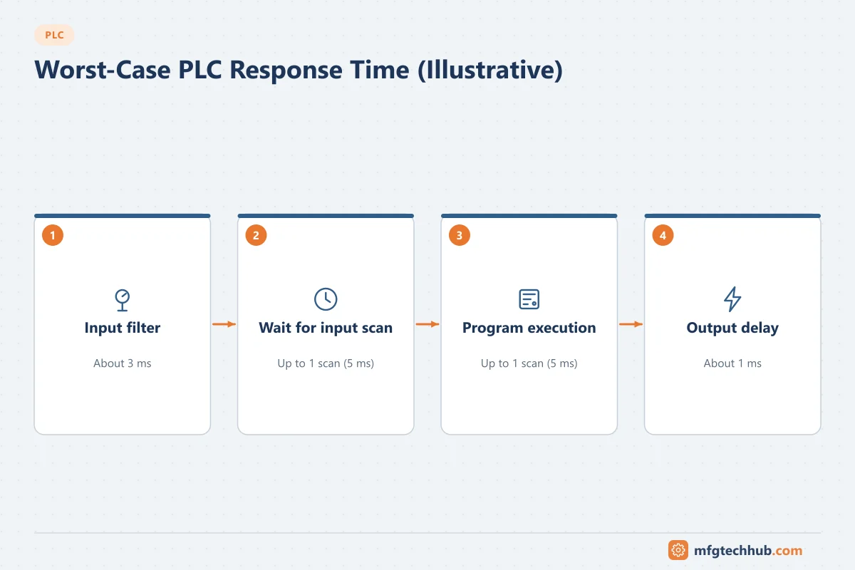
An input change must pass through the input filter, wait for the next input scan, be processed, and be written at the end of the scan. In the worst case, the change arrives just after the input scan, so it waits almost a full scan before being read and another scan before the output is written:
| Component | Example value |
|---|---|
| Input module filter delay | 3 ms |
| Up to 2 × scan time (scan = 5 ms) | 10 ms |
| Output module delay (transistor output) | 1 ms |
| Worst-case response | about 14 ms |
The values are illustrative; use the data sheets of your modules and the measured scan time. If this is too slow for an application, use faster input filters, interrupt (event) tasks, high-speed counter modules or dedicated motion hardware.
Missed pulses
A signal that turns on and off between two input scans is never seen by the program. For example, a 3 ms pulse from a fast sensor is easily missed by a 10 ms scan. Solutions: pulse-stretching in the sensor, high-speed counter inputs, input latching or event-triggered tasks.
Tasks and organisation blocks
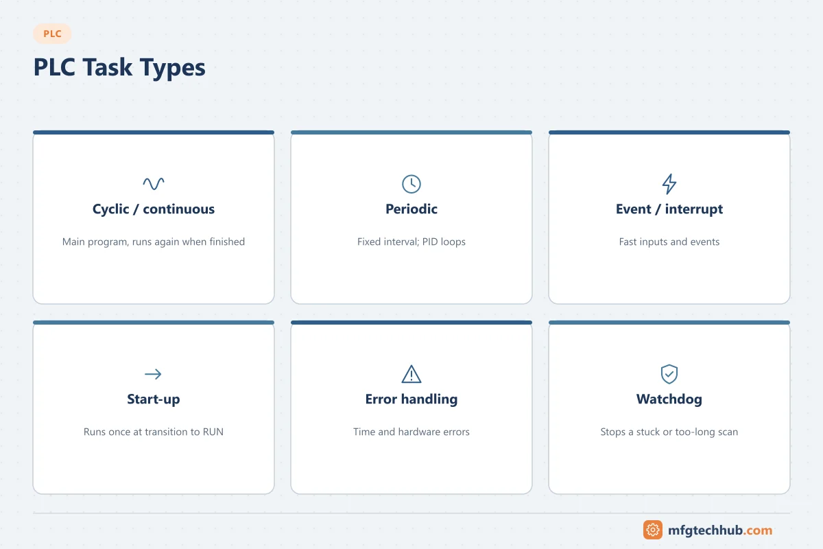
Modern PLCs do not run one single loop; they run several tasks with different triggers:
| Task type | Behaviour | Siemens S7 (examples) | Rockwell Logix |
|---|---|---|---|
| Cyclic / continuous | Runs again as soon as it finishes | OB1 (main program cycle) | Continuous task |
| Periodic / cyclic interrupt | Runs at a fixed interval, interrupting the main cycle | Cyclic interrupt OBs (for example OB30 to OB38) | Periodic tasks |
| Event / hardware interrupt | Runs when an input or event occurs | Hardware interrupt OBs (for example OB40) | Event tasks |
| Start-up | Runs once when the CPU goes to RUN | OB100 | Controller start-up routines (prescan, power-up handler) |
| Error handling | Runs on time or hardware errors | Error OBs (for example OB80 for time errors) | Fault routines |
Put control loops (PID) in periodic tasks so they run at a constant interval; PID algorithms assume a fixed sample time. Keep interrupt tasks short, because they delay everything else.
Synchronous and asynchronous I/O
In the classic model, I/O is updated once per scan. Many current PLCs update I/O asynchronously: Rockwell Logix controllers, for example, receive I/O data at the requested packet interval (RPI) of each module, independent of the program scan. An input value can then change in the middle of a routine. Where consistency matters, copy inputs to internal tags at the start of the routine and work with the copies.
The watchdog
The watchdog is a timer that checks that each scan completes within a configured maximum time. If the program gets stuck (for example in an endless loop) or the scan becomes too long, the watchdog trips and the CPU goes to STOP or runs an error routine, and outputs go to their configured fail-safe state. Set the watchdog time with margin above the normal maximum scan time, and investigate any trip rather than just raising the limit.
Operating modes and memory
| Topic | What to know |
|---|---|
| RUN / STOP / PROGRAM | In STOP, the program does not run and outputs go to their configured state (usually off) |
| Start-up | Warm and cold restarts differ in which data is kept; define start-up behaviour so equipment does not restart unexpectedly |
| Retentive memory | Selected tags (counters, totals, recipe data) keep their values through power loss |
| Output behaviour on stop | Configure per module: off, hold last value or substitute value |
Always consider what the machine does when the PLC goes from STOP to RUN: a sealed-in motor output should not restart by itself after a power failure.
Programming consequences of the scan cycle
| Mistake | What happens | Better practice |
|---|---|---|
| Same output written in two places (“double coil”) | Only the last write in the scan counts; the earlier logic seems to do nothing | Write each output in one place |
| Relying on rung order without noticing | A value calculated below its use is one scan late | Order logic deliberately; document dependencies |
| Long loops in structured text | Scan time grows; watchdog may trip | Limit loop sizes; spread work over scans |
| Edge detection on asynchronous inputs | Edges missed or detected twice | Use buffered copies and proper one-shot instructions |
| PID in the continuous task | Irregular sample time, poor control | PID in a periodic task |
See PLC Programming Best Practices and the PLC Troubleshooting Guide.
Frequently asked questions
What is a PLC scan cycle?
The repeated sequence in which a PLC reads its inputs into memory, executes its program, writes its outputs and handles communication and diagnostics.
What is a typical PLC scan time?
It depends on the CPU and the program. Small programs on current CPUs often run in a few milliseconds or less; large programs take longer. The programming software shows the actual scan time.
Why does my PLC miss short input pulses?
If the pulse starts and ends between two input scans, the program never sees it. Use high-speed counter inputs, input latching, shorter input filters or event-triggered tasks for fast signals.
Key takeaways
- The PLC reads inputs, executes the program on a snapshot, then writes outputs.
- Worst-case response is roughly input delay plus two scans plus output delay.
- Use periodic tasks for PID and event tasks for fast signals; keep interrupts short.
- The watchdog protects against stuck programs; configure fail-safe outputs and start-up behaviour.
Related tutorials
Before you apply this in a plant: this article is for education. Always check the current edition of the relevant standards, the manufacturer's documentation for your exact product and version, and your site's procedures. Safety-related work needs qualified personnel. See our editorial policy.