
PLC Application Examples: Five Worked Control Designs with I/O Lists and Logic
On this page
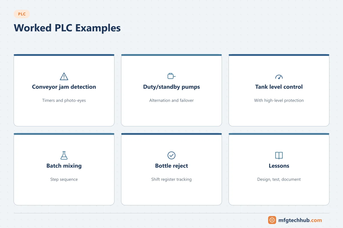
The best way to understand how PLCs are applied is to walk through real control problems. The five examples below are typical small applications that appear in many plants. Each includes an I/O list, a control narrative, key interlocks, and commissioning checks. They are simplified teaching examples; a real design also needs a hazard assessment, electrical design to local codes, and site standards.
How to read these examples
Each example follows the workflow used in real projects: define the function → list the I/O → write the control narrative → define interlocks and alarms → test. Tag names follow a simple convention (area-device-signal). See PLC Project Process and PLC Programming Best Practices.
Example 1: Conveyor with jam detection
Function: A belt conveyor transfers cartons from a packing machine to a palletiser. It must stop if a carton jams at the transfer point or if the downstream conveyor is full.
| Tag | Type | Description |
|---|---|---|
| CV1_RUN_FB | DI | Motor contactor auxiliary contact (running feedback) |
| CV1_JAM_PE | DI | Photo-eye at transfer point (blocked = carton present) |
| CV2_FULL | DI | Downstream full signal from palletiser PLC |
| ESTOP_OK | DI | Safety relay status (monitoring only; safety relay removes power) |
| CV1_START_CMD | DO | Motor contactor coil |
| CV1_ALARM_LAMP | DO | Stack light |
Control narrative:
- In automatic mode, CV1 runs when the upstream machine is running, CV2 is not full and no fault is active.
- If the transfer photo-eye stays blocked for longer than a set time (for example 3 s, adjustable) while the conveyor runs, a jam is declared: the conveyor stops and an alarm is raised. Reset requires the photo-eye to be clear and an operator reset.
- If running feedback is not received within 2 s of the start command, a motor fail alarm is raised and the command is removed.
Logic highlights:
- Jam detection is a timer on the photo-eye that only runs while the conveyor is running, so a stopped conveyor with a carton in front of the eye does not alarm.
- Feedback supervision detects a tripped overload or failed contactor.
- The emergency stop is handled by a safety relay or safety PLC that removes power; the standard PLC only monitors its status.
Commissioning checks: simulate a jam with a carton; disconnect feedback to confirm the motor fail alarm; verify behaviour after an E-stop reset (no automatic restart without a deliberate command).
Example 2: Duty/standby pump station with alternation
Function: Two pumps maintain pressure in a water supply header. One pump runs (duty), the other is standby. Duty alternates to equalise wear.
| Tag | Type | Description |
|---|---|---|
| PT101 | AI (4–20 mA) | Header pressure, 0–10 bar |
| P1_RUN_FB, P2_RUN_FB | DI | Running feedback |
| P1_TRIP, P2_TRIP | DI | Motor protection trip |
| P1_AUTO, P2_AUTO | DI | Local selector in Auto |
| P1_START, P2_START | DO | Start commands |
Control narrative:
- The duty pump starts when pressure falls below the start setpoint (for example 4.0 bar) and stops above the stop setpoint (for example 5.5 bar). The gap is a hysteresis band to prevent short-cycling.
- If the duty pump fails (trip, or no feedback within a set time), the standby pump starts automatically and an alarm is raised.
- If pressure continues to fall below a low-low setpoint with the duty pump running, the standby pump also starts (assist).
- Duty alternates at each start or after a set run time.
- A minimum run time and maximum starts per hour protect the motors.
Logic highlights:
- Scale the analog input and check it for out-of-range values. A failed transmitter (for example below 3.6 mA) should raise an alarm and switch to a defined safe behaviour, not be read as zero pressure. The 4–20 mA calculator shows the scaling and NE 43 limits.
- Alternation uses a simple duty pointer that changes only when both pumps are available.
Commissioning checks: calibrate PT101 at several points; test failover by tripping the duty pump; confirm alternation over several cycles; confirm the maximum starts per hour limit.
Example 3: Tank level control with high-level protection
Function: A buffer tank is filled by an inlet valve and emptied by the process. The PLC maintains level and protects against overflow.
| Tag | Type | Description |
|---|---|---|
| LT201 | AI | Tank level, 0–100 % |
| LSHH201 | DI | Independent high-high level switch |
| XV201_OPEN_CMD | DO | Inlet on/off valve, or FV201 (AO) for a modulating valve |
| XV201_ZSO, XV201_ZSC | DI | Valve open/closed limit switches |
Control narrative:
- For an on/off valve: open below 40 %, close above 70 % (hysteresis).
- For a modulating valve: a PID loop controls level at 60 %. See PID Control Explained.
- High level alarm at 85 %; the independent high-high switch closes the inlet valve regardless of the level transmitter.
- Valve position discrepancy: if the valve is commanded open but not open within its travel time (for example 10 s), raise an alarm.
Logic highlights:
- The high-high trip uses a separate sensor, so a failed level transmitter cannot defeat the overflow protection. If overflow is a significant hazard, this function is assessed as a safety function and may need a safety instrumented system rather than standard PLC logic.
- Limit switches allow valve failure detection.
Commissioning checks: stroke the valve and confirm limit switches and travel time; verify the level transmitter against the tank (sight glass or dip); function-test the high-high switch by raising the level or using a test method approved for the device.
Example 4: Batch mixing sequence
Function: A mixing tank receives two ingredients by weight, mixes for a set time at temperature, then discharges.
| Tag | Type | Description |
|---|---|---|
| WT301 | AI | Tank load cells (weight) |
| TT301 | AI | Temperature (RTD). See RTDs |
| XV301, XV302 | DO | Ingredient A and B inlet valves |
| AG301_START | DO | Agitator motor |
| HV301 | AO | Heating valve |
| XV303 | DO | Discharge valve |
Control narrative (sequence):
| Step | Action | Transition to next step |
|---|---|---|
| 0 Idle | All outputs off | Start command and recipe loaded |
| 1 Charge A | Open XV301 | Weight ≥ target A − in-flight allowance |
| 2 Charge B | Open XV302 | Weight ≥ target A + target B − in-flight allowance |
| 3 Heat and mix | Agitator on, temperature PID active | Temperature within band for set time |
| 4 Discharge | Open XV303, agitator on | Weight below empty threshold |
| 5 Complete | Report actual quantities | Operator acknowledges |
Logic highlights:
- A Sequential Function Chart or a step-number state machine keeps the sequence readable. See PLC Programming Languages.
- In-flight compensation closes the valve slightly before the target to allow for material still falling.
- Hold and abort states let operators pause safely; outputs go to defined states.
- Recipes (targets, temperatures, times) come from the HMI, SCADA or a batch/MES system. The ISA-88 model formalises this structure.
Commissioning checks: calibrate load cells with test weights; tune the in-flight value from actual overshoot; test hold, resume and abort in every step; verify the batch report matches actual quantities.
Example 5: Bottle reject station with shift register
Function: An inspection camera checks bottles on a conveyor. Rejected bottles must be pushed off the line at a reject station a fixed distance downstream.
| Tag | Type | Description |
|---|---|---|
| CAM_RESULT_BAD | DI | Camera reject signal (pulse) |
| BOTTLE_PE | DI | Bottle-present photo-eye at camera |
| ENC_PULSE | High-speed counter | Conveyor encoder |
| REJECT_PE | DI | Confirmation photo-eye after the reject station |
| REJECTOR | DO | Pneumatic pusher solenoid |
Control narrative:
- Each bottle is registered when it passes the camera, with its good/bad result.
- The result is tracked by encoder distance (or a bit shift register clocked by bottle pitch) to the reject station.
- When a bad bottle reaches the station, the pusher fires for a set time.
- A confirmation photo-eye checks that rejected bottles were removed; if a bad bottle passes, the line stops (reject verification).
Logic highlights:
- Encoder-based tracking is robust to speed changes; time-based delays are not.
- Pulses from the camera may be shorter than the PLC scan; use a latched or high-speed input or have the camera hold its output until acknowledged.
- The reject verification step is essential in quality-critical applications (such as pharmaceuticals or food safety).
Commissioning checks: run test bottles marked bad at different line speeds; verify tracking at start/stop; confirm reject verification by blocking the pusher.
Common lessons from these examples
| Lesson | Applies to |
|---|---|
| Always supervise feedback (motor running, valve position) | Examples 1, 2, 3 |
| Treat analog signals as possibly failed, not just scaled | Examples 2, 3, 4 |
| Use hysteresis and minimum times to avoid cycling | Examples 2, 3 |
| Keep safety functions independent of standard logic | Examples 1, 3 |
| Structure sequences as explicit steps or state machines | Example 4 |
| Match fast events to suitable input types | Example 5 |
| Test failure cases, not only normal operation | All |
Frequently asked questions
What is a control narrative?
A control narrative (or functional description) describes in plain language how equipment should behave in each mode and condition: starts, stops, sequences, interlocks and alarms. It is written before programming and used to derive the test procedures.
Why supervise motor running feedback?
Because a command does not guarantee that the motor is running. Feedback supervision detects tripped overloads, failed contactors and local isolation, so the PLC can alarm and switch to backup equipment.
Should safety functions be in the standard PLC?
Safety functions, such as emergency stops or protection against hazardous events, should be implemented with safety-rated equipment designed to the applicable standards (for example ISO 13849, IEC 62061 or IEC 61511). A standard PLC can monitor their status.
Key takeaways
- Every PLC application follows the same path: function, I/O, narrative, interlocks, tests.
- Supervision of feedback and analog signal quality turns simple logic into robust logic.
- Test failure scenarios deliberately during commissioning.
Related tutorials
Before you apply this in a plant: this article is for education. Always check the current edition of the relevant standards, the manufacturer's documentation for your exact product and version, and your site's procedures. Safety-related work needs qualified personnel. See our editorial policy.