
Industrial Robots Explained: Types, Collaborative Applications, Safety Standards and PLC Integration
On this page
Industrial robots handle welding, painting, assembly, machine tending, palletising, picking and inspection in almost every manufacturing sector. For automation engineers, the challenge is rarely the robot alone. It is the robot cell: tooling, safeguarding, PLC integration, vision, material flow and the people working around it.
Safety note: robot applications must be designed, risk-assessed, safeguarded and validated by competent people according to the applicable standards and regulations (for example ISO 10218-1 and -2, ISO 12100, ISO 13849-1 and regional machinery law). This article is an educational overview.
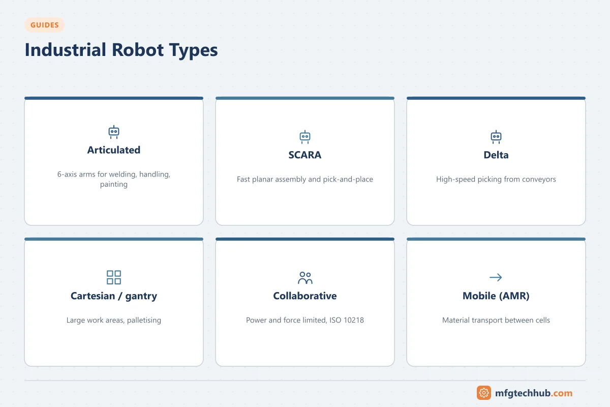
Robot types
| Type | Characteristics | Typical applications |
|---|---|---|
| Articulated (6-axis) | Large, flexible work envelope; reaches around obstacles | Welding, painting, machine tending, assembly, material handling |
| SCARA | Fast, rigid in vertical direction, compliant horizontally | Small-part assembly, pick and place, electronics |
| Delta (parallel) | Very fast, light payloads | High-speed picking and packaging, food handling |
| Cartesian / gantry | Linear axes, large areas, high rigidity | Palletising, machine loading, large workpieces |
| Collaborative-capable robots | Designed with features (for example force limiting) that support collaborative applications | Assembly assistance, machine tending, inspection with people nearby |
| Mobile manipulators | Robot arm on an autonomous mobile robot | Flexible material handling and tending |
Selecting a robot
| Criterion | Questions |
|---|---|
| Payload | Weight of the part plus gripper, including the load’s centre of gravity and inertia |
| Reach and work envelope | Can the robot reach all positions, with suitable orientation? |
| Cycle time | Speed and acceleration with the real payload |
| Repeatability and accuracy | Repeatability is usually excellent; absolute accuracy matters for offline programming and vision-guided tasks |
| Environment | Cleanroom, washdown, food-grade, explosion protection, foundry or welding protection |
| Mounting | Floor, wall, ceiling, track |
| Integration | Supported fieldbuses (PROFINET, EtherNet/IP, EtherCAT), safety communication, PLC libraries |
| Support | Local service, spare parts, training, programming skills available |
End-of-arm tooling (EOAT)
Grippers and tools often decide success: vacuum grippers for flat parts and boxes, mechanical grippers for machined parts, magnetic grippers, welding torches, screwdrivers and dispensers. Include sensors on the tool (part present, gripper open/closed, vacuum level) and consider tool changers for multiple products.
Safety
Standards
- ISO 10218-1:2025 covers safety requirements for industrial robots (the robot itself); ISO 10218-2:2025 covers robot applications and robot cells (integration). The 2025 editions replaced the 2011 editions and incorporate most of the former ISO/TS 15066 guidance on collaborative applications.
- The 2025 editions speak of collaborative applications rather than “collaborative robots”, because safety depends on the whole application (robot, tool, part, speed, layout), not on the robot alone.
- ISO 12100 (risk assessment) and ISO 13849-1 / IEC 62061 (safety-related control systems) apply alongside them. Regional laws (for example the EU machinery rules) define legal obligations.
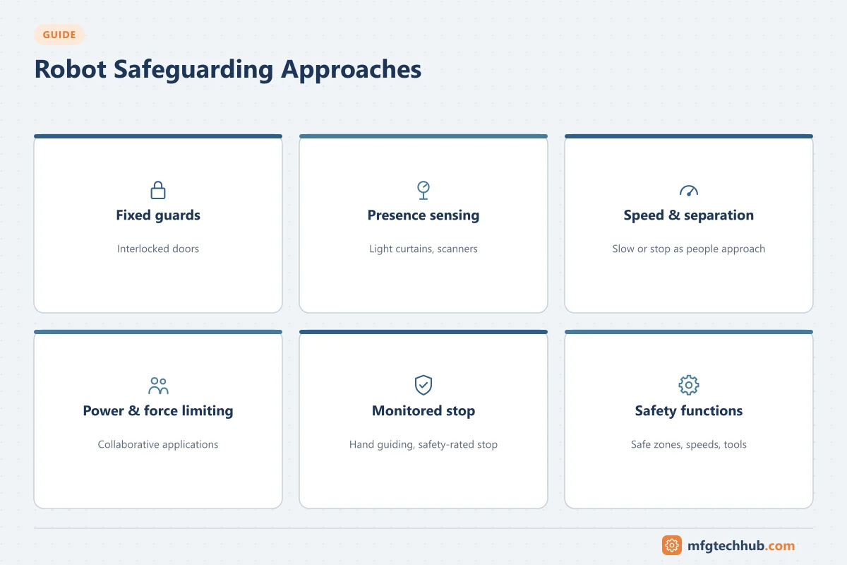
Safeguarding approaches
| Approach | Description |
|---|---|
| Fixed guards and interlocked doors | The classic robot cell; the robot stops safely when a door opens |
| Presence-sensing devices | Light curtains, laser scanners and safety mats that slow or stop the robot when people approach |
| Speed and separation monitoring | Robot speed reduces as people come closer, based on safety-rated sensing |
| Power and force limiting | Robot and application designed so contact forces and pressures stay within limits for the body regions at risk |
| Hand guiding and safety-rated monitored stop | Specific collaborative operating methods |
| Safety-rated robot functions | Safe zones, speed limits and tool orientation limits monitored by the robot’s safety controller |
Key point: a collaborative-capable robot with a sharp tool or a heavy part can still be dangerous. The risk assessment of the application decides the safeguarding.
Integration with PLCs and cell control
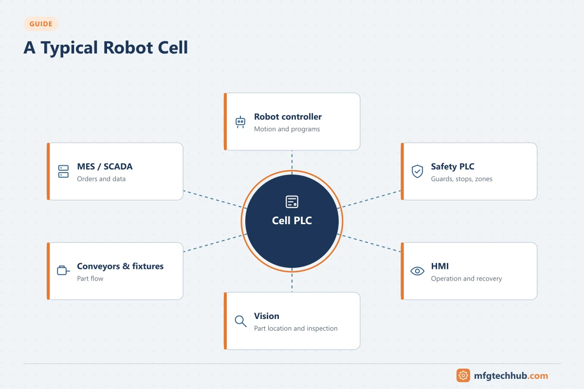
Typical architecture
- Cell PLC coordinates conveyors, fixtures, safety, vision, part tracking and the robot.
- Robot controller runs robot programs (paths, grip/release, error recovery).
- Safety PLC or safety relays handle emergency stops, guards and scanners, often communicating with the robot’s safety controller via safety fieldbuses (for example PROFIsafe or CIP Safety). See Functional Safety.
- HMI for operator control and recovery.
- MES/SCADA for recipes, counts, OEE and traceability.
Common integration patterns
| Pattern | How it works | Considerations |
|---|---|---|
| Handshake with job numbers | PLC sends a program/job number and start; robot reports busy, done and faults | Simple and common; define clear state machine and timeouts |
| PLC-controlled motion (robot libraries) | Some vendors provide function blocks so the PLC programs robot motion | Single programming environment; check vendor support and performance |
| Robot as master of the cell | Robot controller coordinates simple cells | Suitable for small, standalone cells |
Handshake design tips:
- Use a state machine on both sides (idle, running, done, fault, recovery).
- Include heartbeat signals to detect communication loss.
- Define recovery sequences after faults, E-stops and power loss: where is the part, is the gripper holding something, which path returns the robot home safely?
- Keep safety signals on safety-rated paths, not only in standard handshake data.
See PLC Application Examples, Servo Motion Control and PROFINET Explained.
Vision and robots
Vision-guided robots locate parts that are not precisely positioned (bin picking, conveyor tracking), inspect parts, or read codes. Calibration between camera and robot coordinates, lighting and part presentation are the key success factors. See Machine Vision and AI Defect Detection.
Commissioning checklist
- Risk assessment completed and safeguarding installed as designed
- Safety functions validated (every E-stop, door, scanner field, safe zone, speed limit)
- Payload data (mass, centre of gravity) configured correctly in the robot
- Robot and tool frames calibrated; positions taught and verified
- Handshake tested including faults, timeouts and recovery
- Cycle time verified with real parts
- Backups of robot programs and parameters taken. See OT Backup and Restore Runbook
- Operators and maintenance trained on operation, recovery and safe access
Frequently asked questions
What is the difference between a collaborative robot and an industrial robot?
“Collaborative robot” is a common marketing term for robots designed with features such as force limiting. The current ISO 10218 editions focus on collaborative applications: whether a robot can safely work near people depends on the complete application, confirmed by risk assessment.
How does a PLC communicate with a robot?
Usually through an industrial Ethernet protocol such as PROFINET, EtherNet/IP or EtherCAT, exchanging handshake signals (job number, start, busy, done, faults) and, where needed, data such as positions or part information. Safety signals use safety-rated communication or hardwired circuits.
Which robot type is best for palletising?
Four- or five-axis palletising robots and gantry robots are common because of their reach, payload and speed for stacking patterns. The choice depends on payload, pallet pattern, cycle time and floor space.
Key takeaways
- Select robots on payload (including tooling), reach, cycle time, environment and integration capabilities.
- ISO 10218-1/-2:2025 govern robot and application safety; collaborative operation depends on the whole application.
- A cell PLC with clear handshakes, state machines, heartbeats and recovery sequences makes robot cells reliable.
Before you apply this in a plant: this article is for education. Always check the current edition of the relevant standards, the manufacturer's documentation for your exact product and version, and your site's procedures. Safety-related work needs qualified personnel. See our editorial policy.