
How a Factory Works: From Sensor to PLC, SCADA, MES and ERP
On this page
Every modern factory runs on a stack of technologies. Sensors measure temperatures, pressures and flows at the bottom; an ERP system plans orders and books costs at the top; controllers, operator screens, historians and MES sit in between. This guide shows how the layers connect, by following one real process from the pipe to the business system.
-
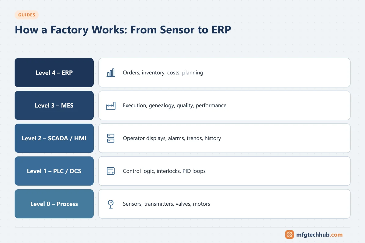
Level 4: Business planning and logistics
ERP · SAP · supply chain
Plans what to make, buys materials and books costs, in days and shifts.
-
Level 3: Manufacturing operations
MES · MOM · historian · batch · quality
Executes orders, tracks materials and genealogy, records quality and performance.
-
Level 2: Monitoring and supervisory control
SCADA · HMI · DCS operator stations · alarms
Gives operators a live view of the process, alarms and trends, and sends supervisory commands.
-
Level 1: Basic control, sensing and manipulation
PLC · DCS controllers · I/O · drives
Reads sensors, runs control loops and interlocks, and drives valves and motors, in milliseconds.
-
Level 0: The physical process
Sensors · transmitters · valves · motors
Where material is actually heated, mixed, moved and measured.
The diagram above shows the layers using the widely used ISA-95 / Purdue levels (0–4), plus the technologies that run across all of them. Each layer links to the tutorials where you can go deeper.
The example: a milk pasteuriser
We will follow a high-temperature short-time (HTST) pasteuriser in a dairy. Raw milk is pumped through a plate heat exchanger, heated to the pasteurisation temperature (commonly at least 72 °C for 15 seconds, or the equivalent required by local regulations), held in a holding tube, then cooled.
It is a good example because it touches every layer:
- It has a control loop (temperature control of the hot water that heats the milk).
- It has a safety function (a flow diversion valve that sends under-temperature milk back rather than forward).
- It produces regulated records (temperature charts that prove every litre was pasteurised).
- It is scheduled by production orders and consumes materials that must be traceable.
Step 1: The physical process (Level 0)
Milk flows through pipes, pumps, heat exchanger plates and a holding tube. Physics decides what happens: heat transfer depends on flow rate, temperature difference and fouling of the plates. Nothing in the stack above can change the physics; it can only measure and act on it.
What can go wrong here: plate fouling reduces heat transfer; a leak between raw and pasteurised sides could contaminate product. Pasteurised milk is therefore kept at a higher pressure than raw milk in the regeneration section, so any leak flows from clean to raw, and that pressure difference is measured.
Step 2: Sensors (Level 0)
Sensors convert physical conditions into electrical signals:
- Temperature at the end of the holding tube: typically a Pt100 RTD, chosen for accuracy and stability. See RTDs vs Thermistors and try the RTD calculator.
- Flow of milk: often a magnetic flowmeter, suitable for conductive liquids and hygienic designs. See Electromagnetic and Ultrasonic Flowmeters.
- Pressure on raw and pasteurised sides: pressure transmitters with hygienic diaphragm seals. See Pressure Transmitters.
- Level in the balance tank: a level transmitter or level switches.
What can go wrong here: sensors drift, fail or are installed badly. This is why instruments are calibrated and why critical measurements are often duplicated. See Calibration.
Step 3: Transmitters and signals (Level 0 to 1)
A transmitter converts the sensor output into a standard signal that travels to the control system, most often 4–20 mA, frequently with HART digital data on top. Newer plants may use fieldbus, PROFINET or Ethernet-APL directly to the device.
Why 4–20 mA? Because 0 mA can be recognised as a broken wire, the loop can power the transmitter, and current is not affected by cable resistance. The 4–20 mA calculator shows the scaling and the NAMUR NE 43 fault levels.
What can go wrong here: wrong range configured in the transmitter vs the PLC, ground loops, damaged cables.
Step 4: The controller: PLC or DCS (Level 1)
The analog signals enter I/O modules of a PLC (common in dairy skids) or a DCS (common in large continuous plants). The controller runs its program in a cycle of milliseconds. See How PLCs Work and DCS vs PLC.
For the pasteuriser, the controller:
- Scales the 4–20 mA signals to °C, bar and m³/h and checks them for faults.
- Runs a PID loop that adjusts the hot water temperature so the milk reaches its setpoint. See PID Control Explained.
- Runs sequences: start-up, production, cleaning-in-place (CIP), shutdown.
- Enforces interlocks: for example, the booster pump may only run when the pressure differential is correct.
Step 5: Control logic and safety
Two kinds of logic are at work, and they must be kept distinct:
- Control logic keeps the process at its targets (temperature, flow, level) efficiently.
- Protective logic keeps the process safe and compliant whatever the control logic does. In our pasteuriser, if the holding-tube temperature falls below the legal limit, the flow diversion valve must send milk back to the balance tank.
In dairy practice, the diversion function is implemented with dedicated, tested instruments and logic as required by food safety regulations. In chemical and energy plants, the equivalent concept is a safety instrumented system designed to IEC 61511. The principle is the same: protection must not depend on the normal control system working correctly. See Functional Safety Explained.
Step 6: Actuators (Level 0)
The controller’s decisions reach the process through actuators:
- A control valve (with a positioner) modulates hot water or steam. See Actuators and Control Valves.
- Motors drive pumps, often through VFDs so flow can be adjusted. See VFDs and Soft Starters.
- On/off valves (like the flow diversion valve) route product.
Closing the loop: the sensor measures, the controller compares with the setpoint, the actuator acts, the process responds, and the sensor measures again. See Open-Loop vs Closed-Loop Control.
Step 7: HMI and SCADA (Level 2)
Operators do not watch PLC code; they use HMI screens and SCADA systems:
- Live values, equipment states and trends.
- Alarms when something needs attention (for example, a temperature deviation or a diverted flow).
- Commands: start production, start CIP, change a setpoint within limits.
Good operator displays show abnormal situations clearly, and a good alarm system only alarms when the operator must act. See SCADA Systems and Setting Up SCADA Alarms.
Step 8: The historian
A historian stores time-series data such as temperatures, flows and valve positions with timestamps, compressed efficiently for years of storage.
For the pasteuriser, the historian (or a dedicated recorder) provides the proof of pasteurisation: an unbroken temperature record and diversion events for every production run. Engineers also use historian trends to tune loops and investigate problems. See Industrial Historians Explained.
Step 9: MES: manufacturing operations (Level 3)
The Manufacturing Execution System manages production as orders and batches rather than as signals:
- It receives the production order (for example, “pasteurise 20,000 L of whole milk for product X”).
- It records which raw milk silos and tankers were used (genealogy), when the run started and stopped, and the quantity produced.
- It collects quality results from the lab, links them to the batch, and releases or holds product.
- It calculates performance such as downtime and OEE.
See What Is MES? and MES Integration Guide. For batch processes, the ISA-88 model structures recipes and equipment.
Step 10: Data and analytics
With data from the historian, MES and lab combined, engineers can answer questions no single system can:
- Which silos and seasons lead to faster plate fouling?
- How much energy per litre does each line use, and when?
- How often does the diversion valve operate, and why?
This requires context: process values tied to batches, products and equipment. See Manufacturing Data Analytics.
Step 11: AI and advanced analytics
Once data is reliable and contextualised, AI methods become useful:
- Predictive maintenance of pumps and homogenisers from vibration and current data.
- Anomaly detection that spots unusual heating behaviour before it causes diversion.
- Soft sensors that estimate quality from process data between lab samples.
AI works in the advisory and optimisation layers; it does not replace the protective logic in Step 5. See AI in Manufacturing and AI and Machine Learning in Process Control.
Step 12: ERP and SAP (Level 4)
Finally, the ERP system (for example SAP) sees the business result:
- The production order is confirmed with actual quantities.
- Raw milk consumption and finished product are posted to inventory.
- Costs are calculated from materials, energy and labour.
- Planning uses actual output to schedule the next days.
The interface between MES and ERP is defined in terms of orders, materials and performance, following ISA-95. See ISA-95 Explained, SAP for Manufacturing and SAP–MES Integration.
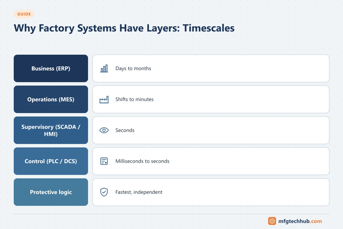
Timescales: why different layers exist
| Layer | Typical timescale | Example decision |
|---|---|---|
| Protective logic | Milliseconds | Divert milk if temperature is below the limit |
| Control (PLC/DCS) | Milliseconds to seconds | Adjust the hot water valve |
| Supervisory (SCADA/HMI) | Seconds to minutes | Operator starts CIP after a product run |
| Operations (MES) | Minutes to shifts | Start the next order; release a batch |
| Business (ERP) | Shifts to months | Plan production; buy materials; report costs |
Each layer works at the speed its decisions need. Putting a decision in the wrong layer causes problems: plant-safety logic in a cloud application would be too slow and too fragile; purchasing decisions in a PLC would be absurd.
Where networks, IIoT and cybersecurity fit
These technologies are not a layer of their own. They connect and protect all layers.
- Industrial networks and protocols carry data between layers: 4–20 mA and HART at the field, PROFINET, EtherNet/IP or Modbus TCP between controllers and I/O, OPC UA from controllers to SCADA and MES, MQTT from edge devices to brokers and cloud platforms. See Industrial Communication Protocols, OPC UA Explained and MQTT and Sparkplug B.
- IIoT and edge computing collect data from machines and sensors that were not connected before, buffer it (store-and-forward) and pass it to historians, MES or cloud analytics. See Industrial IoT.
- Cloud platforms host analytics, enterprise dashboards and increasingly parts of MES; the time-critical layers stay on site.
- Cybersecurity separates the layers into zones connected by controlled conduits, with an industrial DMZ between plant and business networks. See ISA/IEC 62443.
A simplified data path looks like this:
Sensor → transmitter → PLC/DCS → (OPC UA) → SCADA and historian → (OPC UA / MQTT via edge) → MES and data platform → analytics and AI → (APIs / middleware) → ERP
Real systems do not fit neatly into levels
The ISA-95 levels are a model, not a rule. Even the models differ slightly: the Purdue reference model, widely used in cybersecurity, places basic control (PLCs and DCS controllers) at Level 1 and supervisory systems at Level 2, while ISA-95 describes Level 1 as sensing and manipulating the process and includes automated control in Level 2. The diagram on this page follows the common Purdue-style placement. In practice:
- A DCS includes controllers (Level 1–2), operator stations (Level 2) and often a historian and batch manager (Level 3).
- A SCADA package may include a historian and MES-like functions such as OEE.
- Cloud MES runs Level 3 functions outside the plant, with edge components on site.
- ERP systems can include manufacturing functions that overlap with MES.
Use the levels to ask the right questions (“how fast must this decision be?”, “what must keep working if the network fails?”, “who owns this data?”), not to force every product into one box.
Who works at each layer
| Layer | Typical roles |
|---|---|
| Process and instruments | Instrumentation engineers and technicians, process engineers |
| Control | PLC/DCS engineers, control engineers, electrical engineers |
| Supervisory | SCADA engineers, HMI designers, alarm management specialists |
| Operations | MES engineers and consultants, quality and validation specialists |
| Business | ERP/SAP manufacturing consultants, planners |
| Across layers | OT network engineers, OT cybersecurity specialists, integration engineers, industrial data engineers |
See the Automation Engineer Roadmap for learning paths for each role.
Industry examples
See how the same stack is applied in different industries: pharmaceuticals, food and beverage, water and wastewater, oil refining, power generation, cement, steel and mining, automotive and semiconductors.
Where to start
- New to automation: start at the bottom. Learn instrumentation, then PLCs, then SCADA.
- From IT or software: start with the ISA-95 model, industrial protocols and IIoT, then learn enough about PLCs to understand the data you are collecting.
- From business systems (ERP/SAP): start with MES and the MES integration guide, then work downwards.
Frequently asked questions
What is the difference between PLC, SCADA, MES and ERP?
A PLC controls equipment in real time. SCADA lets operators supervise and command many controllers. MES manages production orders, materials, quality and performance on the shop floor. ERP manages the business: planning, purchasing, inventory and finance. Each works at a different timescale and level of detail.
What are the ISA-95 levels?
Level 0 is the physical process, Level 1 is sensing and manipulating the process, Level 2 is monitoring and supervisory control, Level 3 is manufacturing operations management (MES) and Level 4 is business planning and logistics (ERP).
Where does IIoT fit in a factory architecture?
IIoT spans the levels. It connects sensors, machines and controllers to data platforms, often through edge devices using OPC UA and MQTT, and makes their data available to historians, MES, analytics and cloud applications.
Why are safety functions separate from normal control?
So that protection still works if the control system fails or is configured wrongly. Standards such as IEC 61511 (process industry) require safety functions to be independent and designed to a defined integrity level.
Key takeaways
- A factory’s technology is a stack: process, sensors, controllers, supervisory systems, operations systems and business systems.
- Each layer works at its own timescale; decisions belong in the layer that matches their speed and consequence.
- Networks, IIoT, cloud and cybersecurity connect and protect every layer.
- Learning one layer is easier when you know how it connects to the others.
Before you apply this in a plant: this article is for education. Always check the current edition of the relevant standards, the manufacturer's documentation for your exact product and version, and your site's procedures. Safety-related work needs qualified personnel. See our editorial policy.