
How a Thermal Power Plant Works: Boiler, Turbine and Generator Control, BMS, DCS and Grid Requirements
On this page
Thermal power plants convert fuel energy into electricity through a water–steam cycle (and, in combined-cycle plants, a gas turbine). The automation challenge is to follow grid demand quickly and efficiently while protecting very large, high-energy equipment. Plants typically combine a DCS for unit control with specialised systems for burners, turbines, generators and electrical protection.
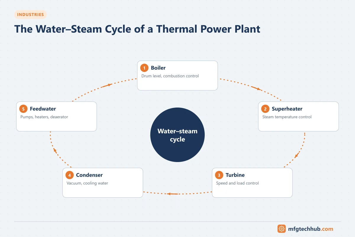
The water–steam cycle
- Feedwater is pumped to high pressure and preheated.
- The boiler (or heat recovery steam generator, HRSG, in combined-cycle plants) turns water into superheated steam.
- Steam expands through the steam turbine, driving the generator.
- Exhaust steam is condensed in the condenser, cooled by cooling water (cooling towers, river or sea water).
- Condensate returns to the feedwater system.
In a combined-cycle plant, a gas turbine drives a generator, and its hot exhaust feeds the HRSG, which produces steam for a steam turbine. This raises overall efficiency compared with a simple steam cycle.
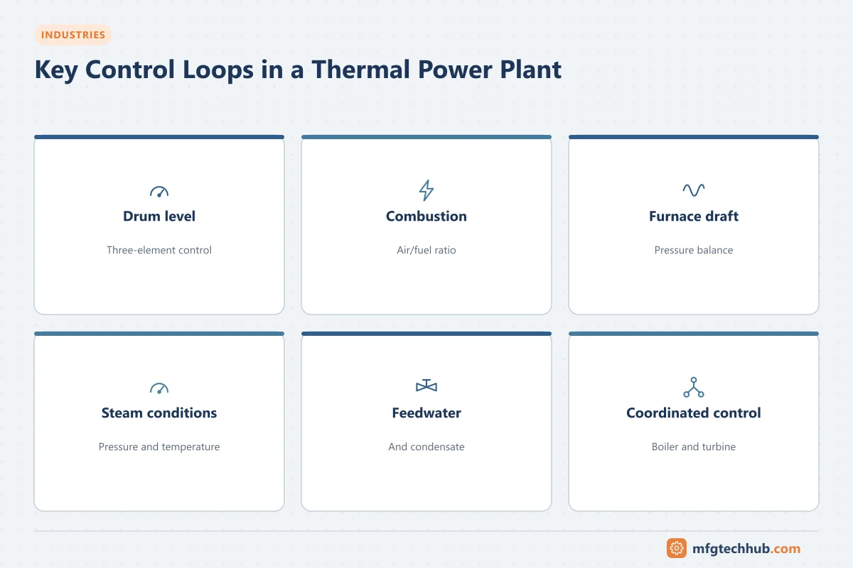
Key control loops
| Loop | Purpose | Notes |
|---|---|---|
| Drum level (drum boilers) | Keep water level within limits despite swell and shrink | Commonly three-element control (level, steam flow, feedwater flow). See Boiler Drum Level Control |
| Combustion control | Match fuel and air to steam demand while keeping safe excess air | Air/fuel ratio with cross-limiting so air leads on load increase and fuel leads on decrease; O₂ trim |
| Furnace draft | Keep furnace pressure slightly negative (balanced draft) | Induced-draft fan control, fast response |
| Main steam pressure and temperature | Protect turbine and boiler, maintain efficiency | Attemperation (spray) for temperature control |
| Feedwater and condensate | Supply water to boiler and manage deaerator and hotwell levels | Pump speed or valve control |
| Coordinated boiler–turbine control | Share load changes between boiler firing and turbine valves | Balances fast response (turbine) with slow boiler dynamics |
See PID Control Explained and Control Strategies in DCS.
Safety and protection systems
| System | Role |
|---|---|
| Burner management system (BMS) | Safe burner light-off, purge, flame monitoring and fuel trip; in the US, NFPA 85 is a key reference for boiler combustion safety |
| Turbine control and protection | Speed and load control, overspeed protection, trips on vibration, bearing temperature, low lube oil pressure and other conditions |
| Generator protection | Protection relays for faults, loss of excitation, reverse power and other abnormal conditions |
| Electrical protection and switchgear | Transformer, bus and feeder protection. See Switchgear and Power Distribution |
| Machinery protection | Vibration monitoring for turbines, fans and pumps |
These systems use safety-rated, often redundant or voting architectures, and their trips must work independently of normal control. See Functional Safety.
Generator and grid
- Excitation system and automatic voltage regulator (AVR) control generator voltage and reactive power.
- Synchronisation matches voltage, frequency and phase before connecting to the grid.
- Frequency response and load control: grid operators may require primary frequency response and automatic generation control (AGC) signals that change the plant’s output setpoint.
- Grid codes define technical requirements such as ramp rates, reactive power capability and fault ride-through.
Automation architecture
| Layer | Typical systems |
|---|---|
| Field | Pressure, temperature, flow and level instruments, flame scanners, analysers (O₂, emissions), valves, drives |
| Control and protection | DCS for unit control; BMS; turbine control system; excitation; protection relays; machinery protection |
| Supervisory | DCS operator stations, alarm management, historian |
| Plant information | Performance monitoring (heat rate), emissions reporting, maintenance systems |
| Business and grid | Energy trading, dispatch interfaces, ERP |
Emissions and performance
- Continuous emissions monitoring systems (CEMS) measure pollutants such as NOx, SO₂, CO and particulates for regulatory reporting.
- Performance monitoring calculates heat rate and component efficiencies to find losses (fouling, air heater leakage, condenser performance).
- Water chemistry monitoring (conductivity, pH, dissolved oxygen, silica) protects the boiler and turbine from corrosion and deposits.
Typical challenges
| Challenge | Good practice |
|---|---|
| Frequent cycling and fast ramps to balance renewable generation | Well-tuned coordinated control, attention to thermal stresses, startup optimisation |
| Ageing control and protection systems | Phased migration with careful testing of protection functions |
| Instrument reliability in harsh conditions | Maintenance and calibration programmes, redundant critical measurements |
| Cybersecurity and grid regulation | Segmentation and utility-sector security requirements |
Frequently asked questions
What is a burner management system?
A safety system that controls the safe startup, operation and shutdown of burners: it enforces furnace purge, supervises ignition, monitors flames and shuts off fuel immediately if unsafe conditions occur.
What is coordinated boiler–turbine control?
A control strategy that adjusts boiler firing and turbine valves together to follow load demand. The turbine can change output quickly using stored steam energy, while the boiler catches up more slowly.
Why is three-element drum level control used?
Because drum level alone gives misleading signals during load changes (swell and shrink). Adding steam flow and feedwater flow measurements lets the controller anticipate demand and keep the level stable.
Key takeaways
- Thermal plants run a water–steam cycle; combined-cycle plants add a gas turbine and HRSG.
- The DCS handles unit control, while BMS, turbine protection, generator protection and relays handle safety-critical functions.
- Grid requirements, emissions monitoring and performance optimisation shape modern plant automation.
Related tutorials
Before you apply this in a plant: this article is for education. Always check the current edition of the relevant standards, the manufacturer's documentation for your exact product and version, and your site's procedures. Safety-related work needs qualified personnel. See our editorial policy.