
Control Valves and Actuators: Types, Positioners, Selection, Sizing and Troubleshooting
On this page
The control valve is the most common final control element in the process industries. It is where the controller’s decision becomes a physical action: more or less flow of steam, cooling water, fuel or product. A well-chosen, well-maintained control valve makes a control loop behave; a sticking or oversized valve can make even perfect tuning useless.
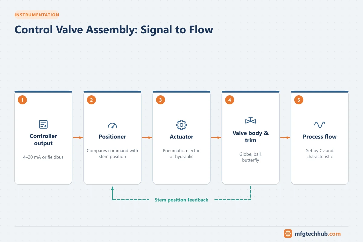
This article covers the parts of a control valve assembly, the main valve and actuator types, fail-safe action, flow characteristics, sizing basics and common problems.
Parts of a control valve assembly
| Component | Role |
|---|---|
| Valve body | Contains the process fluid and the flow-restricting trim |
| Trim | Plug, seat, cage or disc that throttles the flow |
| Actuator | Provides the force to move the trim |
| Positioner | Compares the controller signal with the actual valve position and adjusts the actuator until they match |
| Accessories | Limit switches, solenoid valves, air filter-regulators, volume boosters, position transmitters |
Valve body types
Linear-motion valves
- Globe valves: the traditional choice for accurate throttling. The plug moves up and down relative to a seat. Available in many trim designs for noise and cavitation control.
- Gate valves: designed for fully open or closed service, not for throttling.
- Diaphragm valves: used for corrosive, slurry and hygienic services.
Rotary valves
- Butterfly valves: compact and economical for large pipe sizes; high-performance (double- or triple-offset) designs provide tight shutoff and better control.
- Ball valves: full-bore ball valves are used for on/off service; segmented or V-port balls are used for throttling, including fibrous slurries.
- Eccentric plug valves: combine rotary compactness with good control and shutoff.
| Feature | Globe | Butterfly | V-port ball |
|---|---|---|---|
| Control accuracy | Excellent | Good (high-performance types) | Very good |
| Pressure drop capability | High | Moderate | Moderate to high |
| Cost at large sizes | High | Low | Moderate |
| Typical use | Steam, severe service, accurate control | Water, air, large lines | Slurries, pulp, general process |
Actuator types
Pneumatic actuators
The most common type in process plants. Compressed air (typically 1.4-6 bar supply) acts on a diaphragm or piston against a spring.
- Spring-and-diaphragm actuators: simple, reliable and inherently fail-safe, because the spring moves the valve to a known position when air is lost.
- Piston actuators: provide higher force and longer stroke using higher air pressures; can be spring-return or double-acting.
Electric actuators
Motor-driven actuators are used where compressed air is not available or for remote sites. Modern electric actuators provide accurate modulating control and digital diagnostics, but fail-safe action requires spring-return designs or battery/capacitor backup.
Hydraulic and electro-hydraulic actuators
Provide very high force and fast response, used for large valves, turbine control and pipeline applications.
Positioners
A positioner is essential for most modulating valves. It receives the controller signal (usually 4-20 mA, or digitally via HART, PROFIBUS PA or Foundation Fieldbus), measures the valve stem position, and adjusts the actuator air pressure until the position matches the demand. This overcomes friction and changing process forces.
Digital (smart) positioners also provide valuable diagnostics: friction, stroke time, air leaks, and valve signature tests that help plan maintenance before a valve fails.
I/P converters and solenoid valves
- An I/P converter converts a 4–20 mA signal into a proportional pneumatic signal (commonly 0.2–1.0 bar / 3–15 psi). Older installations use a separate I/P converter with a pneumatic positioner; modern smart positioners include the conversion.
- Solenoid valves in the actuator air supply vent the actuator to drive the valve to its fail-safe position on command, for example from a safety instrumented system. Solenoid and quick-exhaust sizing determine the stroke time in a trip.
- Limit switches or position transmitters confirm valve position to the control or safety system.
Fail-safe action
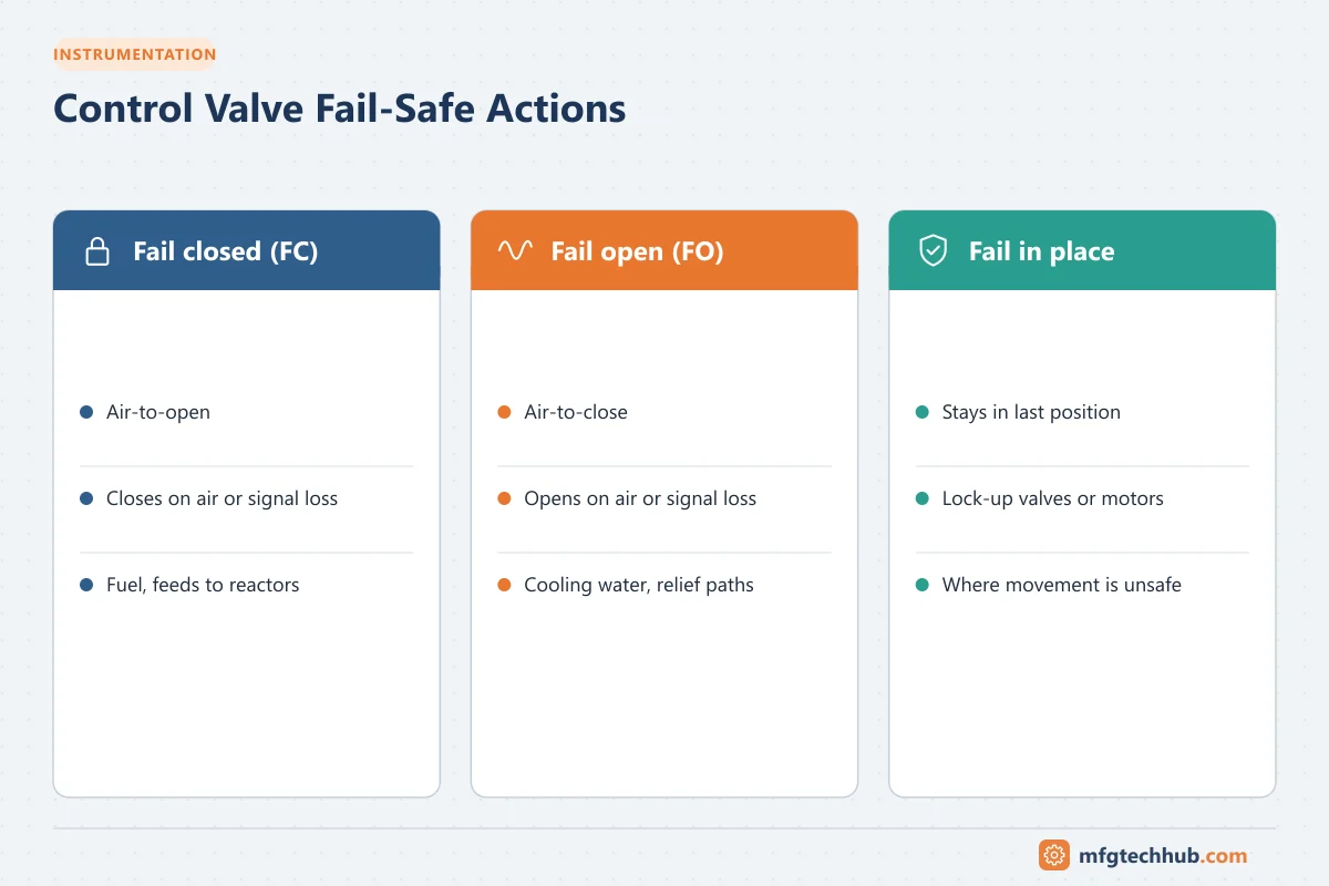
Every control valve must be designed to move to a safe position on loss of air or signal:
| Term | Behavior on air failure | Typical use |
|---|---|---|
| Fail closed (FC) — air-to-open | Spring closes the valve | Fuel gas, steam to a heater, feed to a reactor |
| Fail open (FO) — air-to-close | Spring opens the valve | Cooling water, pressure relief paths |
| Fail last / fail in place | Holds position | Where any movement could be hazardous |
The fail-safe action is decided during process hazard analysis and must match the controller action (direct or reverse) configured in the PLC or DCS.
Flow characteristics
The inherent characteristic describes how flow changes with valve opening at constant pressure drop:
- Linear: flow is proportional to opening. Suits systems where most of the pressure drop is across the valve, such as many level loops.
- Equal percentage: each increment of travel changes flow by the same percentage of the existing flow. It is the most common choice, because it compensates for falling valve pressure drop as flow increases in typical pumped systems.
- Quick opening: large flow change near the closed position; used for on/off and relief applications.
The installed characteristic is what actually happens in the plant, including pipe and equipment pressure losses. Choosing the inherent characteristic that gives a roughly linear installed characteristic makes the loop easier to tune.
How to select a control valve
| Step | Decision | Guidance |
|---|---|---|
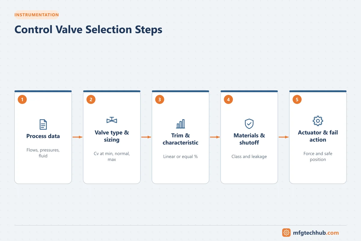
| 1. Process data | Fluid, min/normal/max flow, inlet and outlet pressures at each case, temperature, density, vapour pressure | Sizing requires all operating cases, not just the design case |
| 2. Valve type | Globe, rotary ball, butterfly, eccentric plug, diaphragm, pinch | Globe for precise control and high pressure drop; rotary for high capacity and slurries; butterfly for large low-pressure lines; diaphragm/pinch for hygienic or abrasive services |
| 3. Sizing | Required Cv/Kv at each case | Normal flow around the middle of travel; check choked flow, cavitation, flashing and noise per IEC 60534 / ISA-75.01 |
| 4. Trim and characteristic | Equal percentage, linear, quick opening; anti-cavitation or low-noise trim | Equal percentage suits most process loops with changing pressure drop; linear where pressure drop is nearly constant |
| 5. Materials and pressure class | Body, trim and seat materials; pressure rating | Corrosion, erosion, temperature; piping class |
| 6. Shutoff class | Required seat leakage (for example IEC 60534-4 / ANSI/FCI 70-2 classes) | Tight shutoff costs more and may affect control; specify only what the process needs |
| 7. Actuator | Spring-diaphragm, piston, electric, hydraulic | Thrust/torque with margin at maximum pressure; fail-safe requirement; air supply available |
| 8. Fail-safe action | Fail open, fail closed, fail last position | Decided by process safety analysis |
| 9. Positioner and accessories | Smart positioner, protocol, solenoid, limit switches, volume boosters | Diagnostics, stroke time, safety function requirements |
| 10. Emissions and packing | Fugitive emission requirements | Low-emission packing and bellows seals where required |
| 11. Certifications | Hazardous area for electrical accessories, SIL for safety valves | See Functional Safety |
| 12. Lifecycle | Maintainability, spares, standardisation | Limit variety; consider trim replacement and diagnostics |
Isolation (on/off) valves used in safety functions have different priorities: reliable closure, tight shutoff where required, stroke time and testability (for example partial stroke testing).
Sizing basics: the flow coefficient Cv
A valve’s capacity is expressed by its flow coefficient. In US units, Cv is the flow of water in US gallons per minute at 60 °F with a pressure drop of 1 psi across the valve. For liquids (simplified, non-choked flow):
Q (US gpm) = Cv × √(ΔP (psi) ÷ SG)The metric equivalent Kv is the flow in m³/h of water with a 1 bar drop; Kv ≈ 0.865 × Cv.
Example: a valve must pass 100 gpm of water (SG = 1) with a 16 psi drop. Required Cv = 100 ÷ √16 = 25. Select a valve whose Cv at about 70-80% open is around 25, so it can control across its range.
Full sizing follows IEC 60534 or ISA-75.01 and must check for choked flow, cavitation, flashing and noise.
Rule of thumb: a valve should normally operate between about 20% and 80% open. An oversized valve that works at 5-10% open gives poor control and wears quickly.
Common control valve problems
| Problem | Symptoms | Typical causes |
|---|---|---|
| Stiction (static friction) | Sawtooth PV, square-wave-like output, limit cycling | Tight packing, damaged trim, deposits |
| Deadband / hysteresis | Valve does not respond to small signal changes | Wear, backlash in linkages |
| Oversizing | Poor control at low flow, valve near closed | Conservative sizing, changed process conditions |
| Cavitation | Noise like gravel, erosion damage | High pressure drop on liquids |
| Packing leaks | Visible leakage, emissions | Worn or loose packing |
| Air supply problems | Slow or erratic movement | Leaks, wet or dirty air, undersized tubing |
Many loop “tuning problems” are actually valve problems. Before retuning, stroke the valve in manual and check that it responds smoothly to small steps.
Maintenance tips
- Use positioner diagnostics to trend friction and stroke time.
- Perform valve signature tests during shutdowns to find developing problems.
- Keep instrument air clean and dry.
- Verify fail-safe action and stroke time during functional tests.
Key takeaways
- The control valve and actuator often decide how well a loop performs.
- Positioners and smart diagnostics are essential for modulating valves.
- Fail-safe action must be chosen for process safety and matched in the control configuration.
- Correct characteristic and sizing keep the valve in its good control range.
Related tutorials
Before you apply this in a plant: this article is for education. Always check the current edition of the relevant standards, the manufacturer's documentation for your exact product and version, and your site's procedures. Safety-related work needs qualified personnel. See our editorial policy.