
P&ID Symbols, Lines and Instrument Tags Explained
On this page
P&IDs use a compact graphical language. Once you understand the symbols for equipment, valves, instruments and signal lines, and the letter codes used for instrument tags, you can read almost any P&ID. This article covers the conventions based on ANSI/ISA-5.1, the most widely used standard for instrument symbols and identification.
Every project has its own legend sheets, and company conventions vary. Always check the legend of the drawing you are working with.
Equipment symbols
Equipment is drawn with simplified outlines and labeled with a tag number, such as P-101A (pump), V-201 (vessel) or E-301 (heat exchanger).
| Equipment | Typical symbol |
|---|---|
| Centrifugal pump | Circle with a tangential discharge nozzle |
| Vessel / drum | Rounded rectangle, vertical or horizontal |
| Storage tank | Rectangle with flat or cone roof |
| Heat exchanger | Circle or shell outline with tube-side lines |
| Compressor | Trapezoid or circle with converging lines |
| Column / tower | Tall rounded vessel, often with trays shown |
Equipment prefixes vary by company; common ones are P (pump), V or D (vessel/drum), T (tank or tower), E (exchanger), C or K (compressor) and F (furnace or filter).
Valve symbols
| Valve | Symbol |
|---|---|
| Gate valve | Two triangles point to point (bow tie) |
| Globe valve | Bow tie with a filled circle in the center |
| Ball valve | Bow tie with an open circle |
| Butterfly valve | Line through a circle or bow tie with a vertical bar |
| Check valve | Bow tie with one side filled, or an arrow indicating flow direction |
| Control valve | Valve body with an actuator symbol on top (dome for diaphragm, square or “M” for motor) |
| Pressure safety valve | Angle valve body with a spring symbol |
A control valve symbol often shows the fail-safe action, for example “FC” (fail closed) or “FO” (fail open), or an arrow on the stem. See Actuators and Control Valves.
Instrument bubbles (balloons)
Each instrument or function is drawn as a shape containing its tag. The shape and internal line show what kind of device it is and where it is located:
| Shape | Meaning |
|---|---|
| Circle | Discrete (individual) instrument |
| Circle inside a square | Shared display / shared control, such as a DCS function |
| Hexagon | Computer function |
| Diamond inside a square | PLC function |
| Internal line | Location |
|---|---|
| No line | Field-mounted, near the process |
| Solid horizontal line | Central control room, normally accessible to the operator |
| Dashed horizontal line | Behind a panel or in a rack, not normally accessible |
| Double line | Local panel or auxiliary location |
Example: an FIC shown as a circle inside a square with a solid line is a flow controller in the DCS, available to the control room operator.
Instrument tag letters (ISA-5.1)
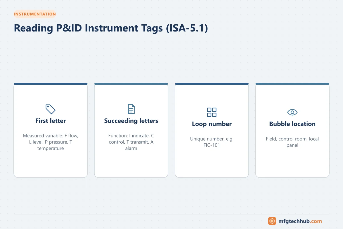
An instrument tag has a functional identification (letters) and a loop number. In FIC-101, “FIC” means Flow Indicating Controller and “101” is the loop number shared by all instruments in that loop.
First letter: the measured or initiating variable
| Letter | Variable | Letter | Variable |
|---|---|---|---|
| A | Analysis | L | Level |
| E | Voltage | P | Pressure |
| F | Flow | S | Speed or frequency |
| H | Hand (manual) | T | Temperature |
| I | Current | W | Weight or force |
| J | Power | Z | Position |
A modifier can follow the first letter: D for differential (PDT, differential pressure transmitter) or Q for integrate/totalize (FQI, flow totalizer).
Succeeding letters: the function
| Letter | Function | Letter | Function |
|---|---|---|---|
| A | Alarm | S | Switch |
| C | Control | T | Transmit |
| E | Primary element (sensor) | V | Valve, final element |
| G | Glass / gauge (local view) | Y | Relay, compute or convert (for example I/P converter) |
| I | Indicate | R | Record |
Common tags
| Tag | Meaning |
|---|---|
| PT-201 | Pressure transmitter |
| TE-305 / TT-305 | Temperature element (sensor) and its transmitter |
| FIC-101 / FV-101 | Flow indicating controller and its flow control valve |
| LG-110 | Level gauge (sight glass) |
| PDI-420 | Differential pressure indicator |
| LSHH-150 | Level switch high-high (trip) |
| TAH-305 | Temperature alarm high |
| FY-101 | Flow relay/converter, often an I/P converter |
| PSV-500 | Pressure safety valve |
Line types
Process lines are drawn as thick solid lines, labeled with line numbers that encode size, fluid, sequence number and pipe specification (for example 4"-HC-1023-A1A). Utility lines are often thinner. Arrows show flow direction.
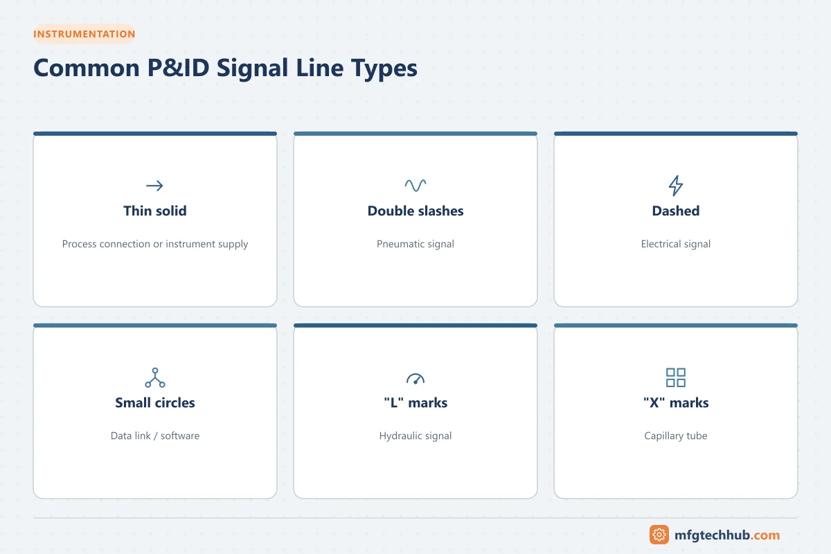
Signal lines use different patterns (ISA-5.1):
| Line pattern | Signal type |
|---|---|
| Thin solid line | Instrument supply or connection to process (impulse line) |
| Line with double slashes (—//—) | Pneumatic signal |
| Dashed line (- - -) | Electrical or electronic signal, such as 4-20 mA |
| Line with small circles (—o—) | Data link / software link inside a system |
| Line with “L” marks | Hydraulic signal |
| Line with “X” marks | Capillary tube (filled system) |
Other common symbols
- Off-page connectors: arrows or pentagons showing where a line continues on another drawing, with the drawing number.
- Reducers: tapered symbol where pipe size changes.
- Spectacle blinds and spades: positive isolation points.
- Drains and vents: small valves at low and high points.
- Interlock symbols: diamonds with “I” and a number, referencing logic diagrams.
- Notes and holds: numbered notes, and “HOLD” clouds for information not yet confirmed.
Tips for learning P&ID symbols
- Keep the project legend open while reading.
- Learn the ISA letter codes first; they unlock most instrument tags.
- Practice by tracing a single control loop from sensor to valve.
- Compare the P&ID with the plant: walking a line in the field makes symbols memorable.
Key takeaways
- Instrument shapes and internal lines tell you the device type and location.
- ISA-5.1 tag letters describe the measured variable and the function.
- Signal line patterns distinguish pneumatic, electrical, software and capillary signals.
- Always confirm conventions with the project’s legend sheets.
Related tutorials
Before you apply this in a plant: this article is for education. Always check the current edition of the relevant standards, the manufacturer's documentation for your exact product and version, and your site's procedures. Safety-related work needs qualified personnel. See our editorial policy.