
How to Read a P&ID: Instruments and Control Loops
On this page
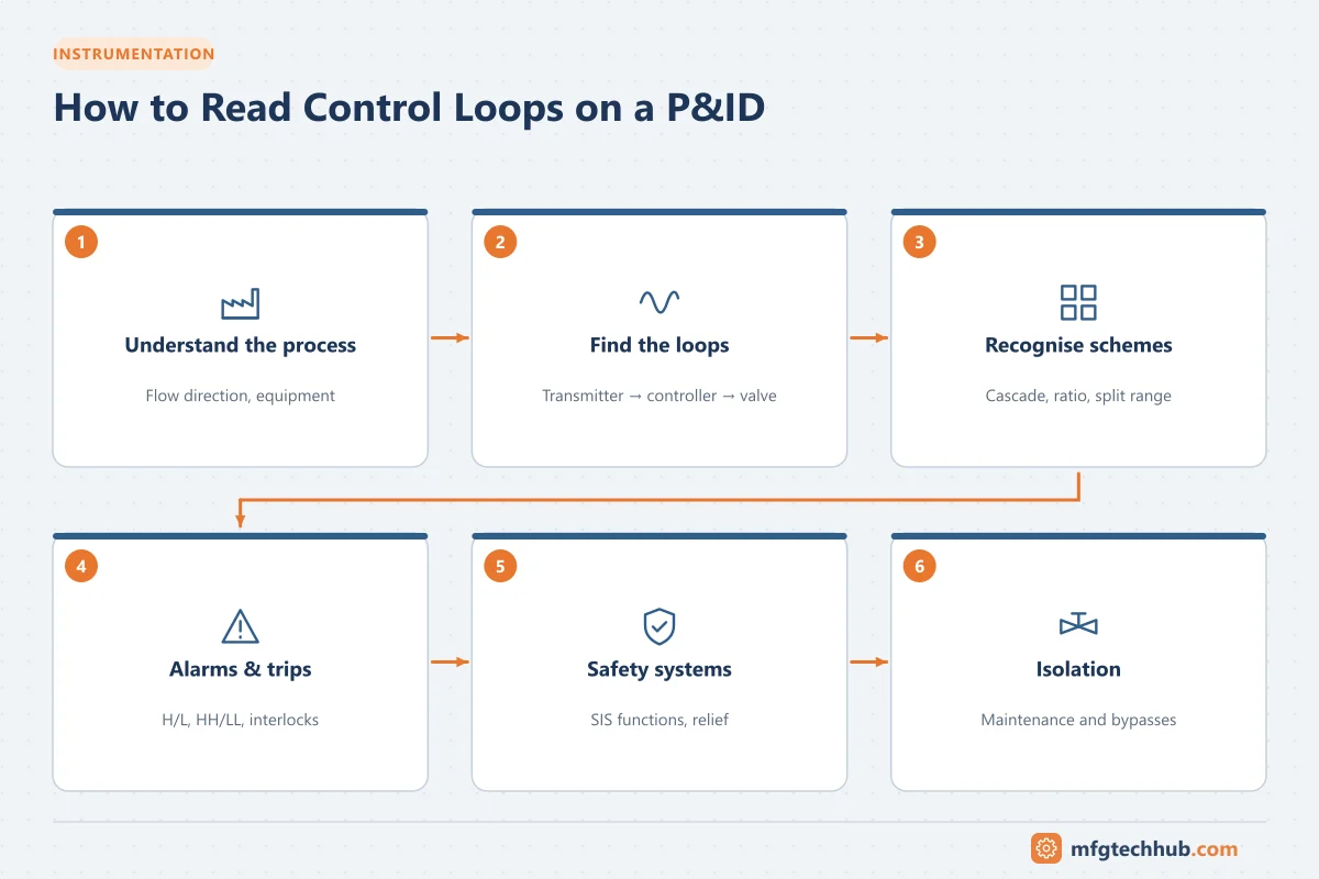
Knowing the symbols is only the first step. The real skill is reading a P&ID as a system: following the process flow, tracing each control loop from sensor to final element, and understanding how alarms, interlocks and safety devices protect the plant. This article walks through a practical method with examples.
If you are new to the symbols, read P&ID Symbols, Lines and Instrument Tags first.
Step 1: Understand the process
Before looking at instruments, answer these questions:
- What comes in, and what goes out?
- What does each major item of equipment do?
- What are the normal operating conditions (from the PFD or process description)?
Trace the main process line with your finger or a highlighter from feed to product. Then note utilities such as steam, cooling water, nitrogen and instrument air.
Step 2: Find the control loops
A control loop on a P&ID is a group of instruments sharing the same loop number. A typical flow loop looks like this:
FE-101 ──► FT-101 ──(4-20 mA, dashed)──► FIC-101 (DCS) ──(dashed)──► FY-101 (I/P) ──(//)──► FV-101
(orifice)  (transmitter)                   (controller)                (converter)          (control valve)
Read it as: the flow element FE-101 measures flow; FT-101 transmits it to the DCS flow indicating controller FIC-101, which sends a 4-20 mA signal to the I/P converter FY-101; this drives the pneumatic control valve FV-101. Many modern valves have a smart positioner instead of a separate I/P converter.
For each loop, identify:
| Question | Where to look |
|---|---|
| What is measured? | First letter of the transmitter tag |
| Where is the controller? | Controller bubble shape (DCS, PLC, local) |
| What does it manipulate? | The final element with the same loop number, or linked by a signal line |
| What is the fail-safe action? | FC/FO markings on the valve |
| What alarms exist? | Letters such as AH, AL, AHH on the bubble or nearby |
Step 3: Recognize common control schemes
Level control
A level transmitter (LT) on a vessel sends to a level controller (LIC), which manipulates either an outlet valve (to control level by draining) or an inlet valve (to control level by filling). Check which, because it determines the controller action.
Temperature control
A temperature element and transmitter (TE/TT) on an exchanger outlet sends to a TIC, which adjusts a steam or cooling water valve (TV).
Cascade control
A cascade appears as one controller’s output going to another controller’s setpoint. Example: TIC-201 (outer loop, reactor temperature) sends its output as the remote setpoint of FIC-202 (inner loop, steam flow), which moves FV-202. The inner loop quickly corrects steam supply disturbances; the outer loop holds temperature.
Ratio control
A flow of one stream (wild flow) is measured, multiplied by a ratio (often shown as FFY or with a “×K” function block), and becomes the setpoint of a second flow controller. Common in blending and combustion air control.
Split range
One controller output drives two valves over different ranges, for example 0-50% opens a cooling valve and 50-100% opens a heating valve. P&IDs usually show this with notes such as “0-50%” and “50-100%” next to each valve.
Pressure control and override
Pressure controllers (PIC) may manipulate a vent, a compressor recycle valve, or a speed setpoint. Selectors (high or low select, shown with “>” or “<” in a function bubble) choose between controllers, for example protecting a compressor from surge while controlling pressure.
Step 4: Find alarms and trips
- Alarms alert the operator: TAH (temperature alarm high), LAL (level alarm low), PAHH (pressure alarm high-high).
- Switches and trips act automatically: LSLL (level switch low-low) may stop a pump to prevent dry running.
- Interlocks are shown with diamond symbols and interlock numbers, referencing cause-and-effect charts or logic diagrams that define exactly what happens.
Step 5: Identify safety systems
Look for:
- Pressure safety valves (PSV) and rupture discs, with set pressures, discharging to flare, vent or a safe location
- Safety Instrumented Functions (SIF), often shown with special tags or symbols linking sensors, a safety logic solver and shutdown valves (XV, SDV or ESDV)
- Emergency shutdown valves with fail-safe action and limit switches
- Fire and gas detectors where applicable
Separate the basic process control system (BPCS) from the safety instrumented system (SIS). They should use independent sensors and final elements where required by IEC 61511.
Step 6: Check isolations and maintenance features
Operations and maintenance use P&IDs to plan work, so note:
- Block valves around control valves and instruments
- Bypass valves around control valves (and their normal position, usually locked or car-sealed closed)
- Drains, vents and sample points
- Blinds and spectacle blinds for positive isolation
- Car-sealed open (CSO) or car-sealed closed (CSC) valves, especially on relief paths
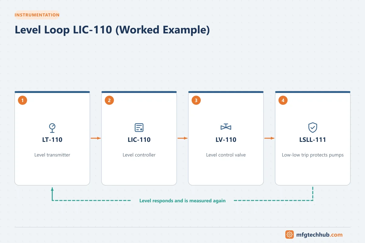
Worked example: a pump suction drum
Imagine a drum V-101 feeding pump P-101A/B:
- LT-110 → LIC-110 → LV-110 on the drum inlet line: the controller keeps level by adjusting the incoming flow.
- LSLL-111 on the drum, separate from LT-110, trips both pumps on low-low level to prevent dry running.
- PT-120 on the pump discharge with PAL-120: a low-pressure alarm indicates a pump problem.
- PSV-101 on the drum protects it against overpressure.
- P-101A/B are duty/standby pumps with suction and discharge block valves and discharge check valves.
From these tags alone, you can explain how the drum is controlled, how the pumps are protected, and how maintenance can isolate one pump while the other runs.
Common mistakes when reading P&IDs
- Ignoring the legend and assuming symbols mean the same thing on every project
- Missing off-page connectors and losing the thread of a line
- Confusing an alarm (operator action) with a trip (automatic action)
- Assuming a valve’s normal position without checking notes (NO/NC, CSO/CSC)
- Using an out-of-date revision
Key takeaways
- Start with the process, then trace loops by their shared loop number.
- Recognize cascade, ratio, split-range and override schemes from how controllers connect.
- Distinguish alarms, interlocks and safety instrumented functions.
- Use P&IDs to understand isolation and maintenance, not just control.
Related tutorials
Before you apply this in a plant: this article is for education. Always check the current edition of the relevant standards, the manufacturer's documentation for your exact product and version, and your site's procedures. Safety-related work needs qualified personnel. See our editorial policy.