
Float, Displacer and DP Level Measurement Explained
On this page
Level measurement is one of the most important functions in industrial instrumentation. Accurate level monitoring helps industries maintain safe operations, optimize production processes, prevent equipment damage, and improve product quality. Whether monitoring water in storage tanks, chemicals in reactors, crude oil in separators, or pharmaceutical ingredients in mixing vessels, selecting the appropriate level measurement technology is critical.
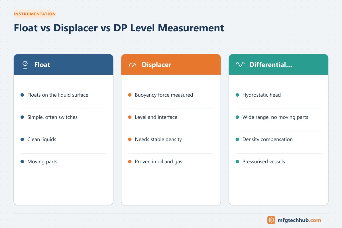
Among the oldest and most widely used technologies are Float Level Measurement, Displacer Level Measurement, and Differential Pressure (DP) Level Measurement. Although modern technologies such as radar and ultrasonic level transmitters are becoming increasingly popular, these traditional methods continue to play a significant role across industries because of their reliability, simplicity, and proven performance.
This article provides a detailed overview of these level measurement technologies, including their principles, construction, applications, advantages, limitations, and best practices.
Why Level Measurement Matters
Level measurement plays a critical role in industrial operations for several reasons:
- Preventing tank overflows
- Avoiding dry running of pumps
- Maintaining product quality
- Optimizing inventory management
- Ensuring process safety
- Supporting automated process control
- Improving production efficiency
In industries such as oil and gas, pharmaceuticals, food processing, water treatment, and power generation, inaccurate level measurements can result in production losses, environmental incidents, equipment failures, and safety hazards.
Understanding Level Measurement Technologies
Level measurement technologies can generally be divided into two categories:
Direct Measurement
Direct measurement physically detects the liquid surface.
Examples:
- Float Level Measurement
- Sight Glasses
- Magnetic Level Indicators
Indirect Measurement
Indirect measurement calculates level based on another parameter.
Examples:
- Differential Pressure
- Radar
- Ultrasonic
- Capacitance
Float, Displacer, and Differential Pressure instruments represent some of the most established industrial level measurement methods.
Float Level Measurement
What is Float Level Measurement?
Float level measurement is one of the simplest and oldest methods used to determine liquid level.
A float rests on the liquid surface and moves up or down as the level changes. This movement is mechanically or electronically converted into a level indication or control signal.
Working Principle
Float measurement operates according to Archimedes’ Principle.
A body immersed in a fluid experiences an upward buoyant force equal to the weight of the displaced liquid.
As liquid level rises:
- Float rises
As liquid level falls:
- Float falls
The movement is transferred through:
- Mechanical linkages
- Magnetic coupling
- Reed switches
- Potentiometers
- Electronic transmitters
to provide level indication.
Basic Float Level Measurement System
Main Components
Float
Typically constructed from:
- Stainless Steel
- Polypropylene
- PVC
- Titanium
The float must have lower density than the liquid.
Guide Rod or Float Arm
Maintains float movement in a defined path.
Transmitter Mechanism
Converts movement into:
- Analog signal (4-20 mA)
- Digital signal
- Mechanical indication
Indicator
Displays liquid level locally or remotely.
Types of Float Instruments
Float Switches
Used for:
- High-level alarms
- Low-level alarms
- Pump control
Float Gauges
Provide local level indication.
Magnetic Float Level Transmitters
Use magnetic coupling to eliminate direct mechanical contact.
Float Tape Gauges
Common in large storage tanks.
Industrial Applications of Floats
Float systems are widely used in:
- Water tanks
- Boiler feedwater systems
- Cooling water reservoirs
- Chemical storage tanks
- Wastewater treatment plants
- Fuel storage tanks
Advantages of Float Measurement
Simple Design
Easy to understand and maintain.
Low Cost
Among the most economical level measurement technologies.
Reliable Operation
Proven technology with decades of successful industrial use.
No Complex Electronics
Suitable for harsh industrial environments.
Limitations of Float Measurement
Not Suitable for High Pressure
Mechanical components may be affected.
Limited Accuracy
Compared to radar or DP transmitters.
Mechanical Wear
Moving parts require periodic maintenance.
Density Dependence
Changes in liquid density can affect performance.
Displacer Level Measurement
What is a Displacer?
Displacer level measurement is based on the change in buoyant force acting on a suspended displacer.
Unlike a float, which rides on the liquid surface, a displacer is heavier than the liquid it measures. It does not float. It hangs from a spring or torque tube and stays partially or fully immersed across the measuring range. As the level rises, more of the displacer is submerged, the buoyant force increases and the displacer’s apparent weight falls. The instrument measures that change in apparent weight and converts it into a level signal.
Working Principle
Displacer technology also relies on Archimedes’ Principle.
The buoyant force acting on the displacer is:
Buoyant Force = Weight of Displaced Liquid
             = ρ × g × A × h
Where:
- ρ = density of the process liquid
- g = gravitational acceleration
- A = cross-sectional area of the displacer
- h = submerged length of the displacer
The apparent weight sensed by the instrument is therefore:
Apparent Weight = Actual Weight of Displacer − (ρ × g × A × h)Because the area and the actual weight are fixed, the apparent weight changes linearly with submerged length. The measuring range equals the length of the displacer. Common displacer lengths are roughly 350 mm to 1,500 mm (14 to 60 inches), although longer units are available.
Main Components
Displacer Element
A sealed cylinder, usually made of stainless steel, with a density greater than the process liquid. Its length sets the measuring range.
Torque Tube or Range Spring
The torque tube is a hollow shaft that twists in proportion to the displacer’s apparent weight while also acting as the pressure seal between the process and the instrument head. Spring-type designs use a calibrated spring instead, with the displacer’s movement sensed magnetically or by an LVDT (linear variable differential transformer).
External Cage (Chamber)
Most industrial displacers are mounted in an external cage connected to the vessel by top and bottom nozzles with isolation valves. The cage lets technicians isolate, drain and service the instrument without shutting down the vessel.
Transmitter Head
Converts torque tube rotation or spring movement into a 4-20 mA signal, often with HART or another digital protocol for configuration and diagnostics.
Interface Measurement
One of the most important uses of displacers is interface level measurement, the boundary between two immiscible liquids with different densities, such as oil over water in a separator. When the displacer is fully submerged in the two liquids, its buoyant force depends on where the interface sits along its length. That makes displacers a long-standing choice for:
- Three-phase separators in oil and gas production
- Oil/water separators and desalters
- Solvent recovery and extraction units
For interface service, the instrument must be calibrated with the specific gravities of both liquids. For accurate results, the density difference between them should be significant; a small difference reduces resolution.
Calibration
Displacers can be calibrated in two ways:
- Wet calibration: the cage is filled with the actual process liquid (or water with a correction for specific gravity) at known levels.
- Dry calibration: calibration weights or a hanging-weight method simulate the buoyant force for each level point, so no liquid is needed.
In both cases, the specific gravity entered in the transmitter must match actual operating conditions, including temperature.
Industrial Applications of Displacers
- Separator and knock-out drum level
- Feedwater heater and condenser hotwell level
- Distillation column bottoms
- High-pressure and high-temperature vessels in refineries and petrochemical plants
- Liquid/liquid interface measurement
Advantages of Displacer Measurement
- Handles high pressures and temperatures well when correctly specified
- Proven, well-understood technology with established calibration practices
- Excellent for interface measurement
- Less sensitive than floats to turbulence and light foam
- Continuous output across the full measuring range
Limitations of Displacer Measurement
- Density dependent: changes in liquid density directly change the reading.
- Limited range: the range cannot exceed the displacer length, so tall vessels need multiple instruments or another technology.
- Mechanical parts: torque tubes can suffer fatigue or friction, and cages must be kept free of blockages.
- Coating and build-up: deposits on the displacer change its weight and volume, causing drift.
- Size and weight: caged displacers are heavy and require structural support and piping work.
Differential Pressure (DP) Level Measurement
What is DP Level Measurement?
Differential pressure level measurement infers liquid level from the hydrostatic pressure exerted by a column of liquid. It is the most widely used continuous level method in the process industries because it uses standard pressure transmitters, which plants already know how to install, calibrate and maintain.
Working Principle
The pressure at the bottom of a liquid column is proportional to its height:
P = ρ × g × hTherefore:
h = ΔP / (ρ × g)Where ΔP is the difference between the pressure at the bottom tapping (the high-pressure side, HP) and the reference pressure (the low-pressure side, LP).
Worked example: A water tank (ρ ≈ 1,000 kg/m³) has a 5 m measuring span.
ΔP = 1,000 × 9.81 × 5 = 49,050 Pa ≈ 49.05 kPa ≈ 490.5 mbarThe transmitter would therefore be ranged approximately 0 to 490 mbar for 0 to 100 percent level, assuming it is mounted at the level of the lower tapping.
Open (Vented) Tanks
In an open tank, the surface of the liquid is at atmospheric pressure. The HP side connects to the bottom of the tank, and the LP side is vented to atmosphere. A simple gauge pressure transmitter is often sufficient.
Closed (Pressurized) Tanks
In a closed tank, vapor or gas pressure above the liquid acts on the entire column. To cancel it, the LP side is connected to the vapor space at the top of the vessel. The transmitter then measures only the hydrostatic head of the liquid.
Dry Leg
The LP impulse line is kept free of liquid. This works when the vapor does not condense at ambient temperature. A drain pot or condensate trap is usually fitted.
Wet Leg
When vapors condense (for example, steam), the LP line fills with liquid anyway. A wet leg deliberately fills the reference line with a stable fill liquid so that its contribution is constant and can be calibrated out. Boiler drum level measurement is a classic wet-leg application.
Zero Suppression and Zero Elevation
The transmitter’s calibrated range must account for any liquid head that is not part of the measured level:
- Zero suppression is required when the transmitter is mounted below the lower tapping. The liquid in the HP impulse line adds a constant pressure, so the lower range value is shifted positive.
- Zero elevation is required with a wet leg. The LP side sees a full column of fill liquid, so at 0 percent level the differential pressure is negative, and the range is shifted accordingly.
Getting these values wrong is one of the most common reasons a DP level loop reads incorrectly after commissioning.
Diaphragm Seals and Capillaries
For corrosive, viscous, crystallizing, sanitary or high-temperature services, remote diaphragm seals with filled capillaries replace impulse lines. They prevent plugging and keep the process away from the transmitter. Engineers must account for:
- The fill-fluid head in the capillaries (treated like a wet leg)
- Temperature effects on the fill fluid, which can cause zero shifts
- Slower response time with long capillaries
Balanced systems, with equal capillary lengths on both sides, reduce but do not eliminate temperature effects.
Density Compensation
Because DP level depends on density, changes in temperature or composition cause measurement error. Common approaches include:
- Configuring the transmitter for the density at normal operating conditions
- Adding a temperature measurement and compensating in the DCS or PLC
- Using a second DP measurement across a fixed height to calculate density continuously
- On boiler drums, compensating for both water and steam density using drum pressure
Industrial Applications of DP Level
- Storage tanks and process vessels in chemical plants
- Boiler drums and deaerators in power generation
- Reactors and mixing tanks
- Pressurized vessels where non-contact technologies are unsuitable
- Tanks with opaque, dirty or foaming liquids that interfere with surface-based methods
Advantages of DP Measurement
- Uses standard, widely available pressure transmitters
- Suitable for high pressures and temperatures
- Not affected by foam, vapor or surface turbulence in the same way as surface-sensing methods
- Measuring range limited only by transmitter span, not by a mechanical element
- Easy to integrate with PLC, DCS and SCADA systems using 4-20 mA, HART or fieldbus protocols
Limitations of DP Measurement
- Accuracy depends on known and stable density
- Impulse lines can plug, freeze or develop leaks
- Wet legs can evaporate or lose fill, causing drift
- Capillary systems are affected by ambient temperature
- Requires two process connections on closed tanks
Float vs Displacer vs DP: Quick Comparison
| Criteria | Float | Displacer | Differential Pressure |
|---|---|---|---|
| Measuring principle | Buoyancy (rides on surface) | Change in buoyant force | Hydrostatic head |
| Output | Switch or continuous | Continuous | Continuous |
| Typical range | Switch point up to tank height (tape gauges) | Displacer length, often 0.35 to 1.5 m | Limited by transmitter span |
| Interface measurement | Possible with special floats | Excellent | Possible with density difference |
| High pressure and temperature | Limited | Good | Very good |
| Effect of density change | Moderate | High | High |
| Moving parts | Yes | Yes | No |
| Maintenance | Cleaning and mechanical checks | Cage, torque tube and calibration checks | Impulse line and seal checks |
| Relative cost | Low | Medium to high | Medium |
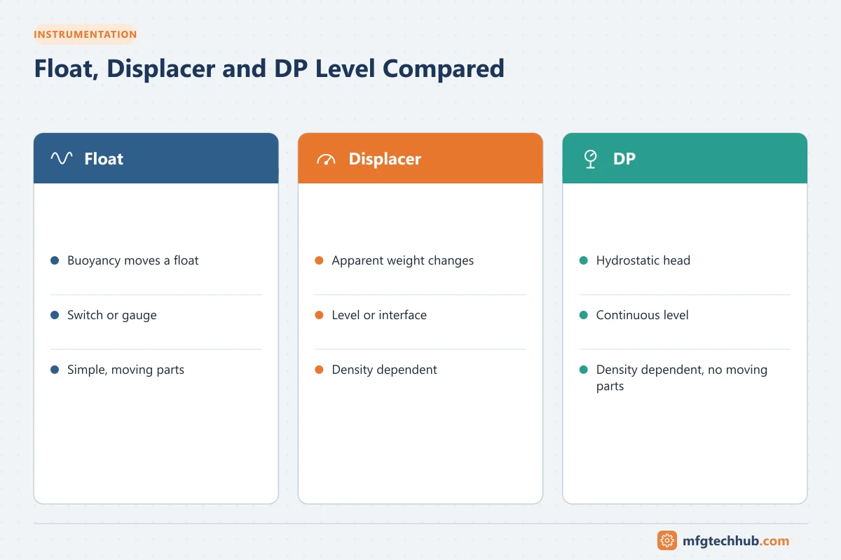
How to Select the Right Technology
Ask the following questions before choosing a level instrument:
- Do you need a switch or a continuous measurement? For simple high and low alarms or pump control, a float switch is often the most economical choice.
- Is the vessel pressurized or at high temperature? Displacers and DP transmitters are generally better suited than floats.
- Do you need to measure an interface? Displacers have a long track record here; guided wave radar is a modern alternative.
- Is the density stable? If density varies significantly, plan for compensation or consider a technology that measures the surface directly, such as radar or ultrasonic level sensors.
- How tall is the measuring range? Long ranges favor DP transmitters over displacers.
- Is the liquid dirty, viscous or corrosive? Use diaphragm seals for DP, or avoid mechanical moving parts.
- What are the maintenance capabilities on site? Choose technology your team can calibrate and troubleshoot confidently.
Installation and Maintenance Best Practices
- Install cages and impulse lines with isolation, vent and drain valves so instruments can be serviced safely.
- Slope impulse lines correctly (liquid-filled lines slope down to the transmitter; gas-filled lines slope up) to avoid trapped gas or liquid.
- Heat-trace and insulate impulse lines and cages where freezing or condensation is possible.
- Verify wet-leg fill levels as part of routine maintenance.
- Record the process density used for calibration and review it whenever the product or operating temperature changes.
- Inspect floats and displacers for coating, corrosion and mechanical damage.
- Compare level readings against a local gauge or sight glass periodically to detect drift early.
For more on pressure transmitter selection, see Pressure Transmitters: Types and Use Cases.
Common Problems and Troubleshooting
| Symptom | Likely Cause | What to Check |
|---|---|---|
| Level reads high or low by a constant amount | Incorrect zero suppression or elevation | Transmitter range values against installed geometry |
| Reading drifts slowly over time | Wet leg losing fill, coating on displacer | Refill wet leg, inspect and clean displacer |
| Reading frozen or sluggish | Plugged impulse line or stuck float | Blow down lines, check float or displacer movement |
| Reading changes with ambient temperature | Capillary fill-fluid expansion | Seal system design, balanced capillaries |
| Reading wrong after product change | Different density | Update specific gravity in calibration |
Typical Applications by Industry
| Industry | Float | Displacer | DP |
|---|---|---|---|
| Oil, gas and petrochemical | Sump and day tanks with simple alarms | Separators, knock-out drums, reflux accumulators, interface service | Pressurised vessels, often with remote seals |
| Chemicals | Non-critical storage with magnetic level gauges | Moderate-vapour applications in external chambers | Corrosive or viscous media with lined remote seals |
| Water and wastewater | Lift-station pump control with float switches | Rarely used | Sludge and wet wells where optical or acoustic methods struggle |
| Food and beverage | Hygienic float gauges for local indication | Rarely used | Process and CIP tanks with hygienic diaphragm seals |
Choosing between technologies? See How to Select a Level Transmitter, which compares radar, guided wave radar, ultrasonic, DP, displacer and other methods.
Frequently Asked Questions
Do floats or displacers work with foam?
Light foam is usually manageable for displacers, because the measurement depends on buoyancy in the liquid, but foam can affect floats. For persistent foam, consider guided-wave radar or DP measurement. See Radar vs Ultrasonic Level Sensors.
How do density changes affect DP level measurement?
DP measures hydrostatic pressure, which equals level × density × g. If temperature or composition changes the density, the indicated level is wrong unless the density is compensated. Use the DP level calculator to see the effect.
Can DP transmitters measure level in pressurised tanks?
Yes. Connect the high-pressure side to the bottom of the vessel and the low-pressure side to the vapour space (dry leg, wet leg or remote seal), so that the vapour pressure cancels out.
When is a float switch still the best choice?
For simple pump control, high-level alarms and local indication in clean liquids, float switches are economical and easy to maintain. Safety-related overfill protection needs a device and design that meet the required safety integrity.
Conclusion
Float, displacer and differential pressure instruments remain the backbone of level measurement in many plants. Floats are simple and economical for switching and basic indication. Displacers are dependable for pressurized vessels and interface service within a limited range. DP transmitters provide flexible, continuous measurement across a wide range of vessel sizes and process conditions.
The right choice depends on the process fluid, vessel conditions, required accuracy, and the plant’s ability to maintain the instrument over its lifetime. Understanding the physics behind each method, especially the role of density, helps engineers select, calibrate and troubleshoot level measurement systems with confidence.
Before you apply this in a plant: this article is for education. Always check the current edition of the relevant standards, the manufacturer's documentation for your exact product and version, and your site's procedures. Safety-related work needs qualified personnel. See our editorial policy.