
Motor Protection Relays and Overload Detection Systems
On this page
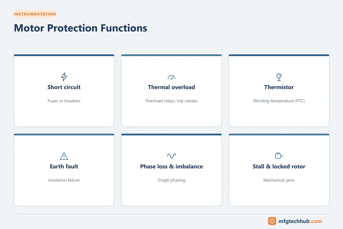
Motors fail expensively. A burnt-out winding means downtime, repair costs and sometimes lost product. Most failures are caused by conditions that protection devices can detect early: overload, phase loss, unbalance, stalling, earth faults and overheating. This article explains the main motor protection functions, the devices that provide them, and how to set them sensibly.
What can go wrong with a motor
| Condition | Effect on the motor |
|---|---|
| Overload | Excess current heats the windings and degrades insulation |
| Short circuit | Very high fault current; risk of fire and severe damage |
| Phase loss (single phasing) | Remaining phases carry much higher current; rapid overheating |
| Voltage unbalance | Negative-sequence currents heat the rotor disproportionately |
| Locked rotor / stall | Current stays at starting level; windings overheat within seconds |
| Earth (ground) fault | Insulation failure to earth; shock and fire risk |
| Undervoltage | Higher current to maintain torque; possible stalling |
| Too many starts | Repeated high starting currents overheat the motor |
| Underload | Indicates dry-running pumps, broken belts or couplings |
A useful rule of thumb from insulation engineering is that every sustained 10 °C above the insulation class limit roughly halves insulation life, which is why overheating protection matters so much.
Short-circuit protection
Fuses or circuit breakers (including motor protection circuit breakers, MPCBs) interrupt short-circuit currents. They must be coordinated with the contactor and overload relay so that a fault does not damage the starter. IEC 60947-4-1 defines Type 1 coordination (damage to the starter is acceptable after a short circuit) and Type 2 coordination (the starter must remain usable, with only light contact welding allowed).
See Industrial Circuit Breakers and Fuse Protection.
Thermal overload relays
The classic overload relay models motor heating:
- Bimetallic overload relays use strips that bend when heated by motor current.
- Electronic overload relays measure current and calculate thermal load digitally, with better accuracy and additional features such as phase-loss detection.
Trip classes
Overload relays are rated by trip class, which defines the maximum time to trip at 7.2 times the current setting (IEC 60947-4-1):
| Trip class | Maximum trip time at 7.2 × setting | Use |
|---|---|---|
| Class 10 | 10 s | Standard motors with normal starting |
| Class 20 | 20 s | Heavier starting loads |
| Class 30 | 30 s | High-inertia loads such as large fans and centrifuges |
Setting overload relays
- Set the current to the motor’s full-load current (FLC) from the nameplate, adjusted for service factor if the application allows.
- Choose a trip class that allows the motor to start but protects it during a stall.
- Do not increase settings to “stop nuisance trips” without finding the cause; repeated trips usually indicate a real problem.
Thermistor protection
PTC thermistors embedded in the stator windings measure winding temperature directly. A thermistor relay trips when resistance rises sharply at the rated temperature. This protects against causes that current-based relays cannot detect, such as blocked ventilation, high ambient temperature or running a VFD-fed motor at low speed.
Motor protection relays (multifunction)
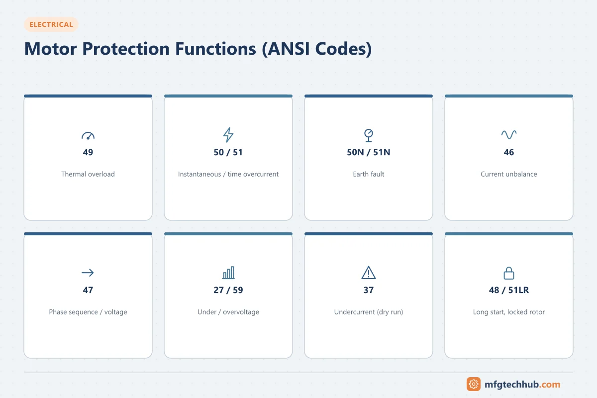
For medium-voltage motors and critical low-voltage motors, motor protection relays combine many functions in one device. Protection functions are often described using ANSI/IEEE C37.2 device numbers:
| ANSI number | Function |
|---|---|
| 49 | Thermal overload (thermal model) |
| 50 / 51 | Instantaneous / time overcurrent (short circuit) |
| 50N / 51N (or 50G) | Earth (ground) fault overcurrent |
| 46 | Negative sequence / current unbalance / phase loss |
| 47 | Phase sequence voltage |
| 27 / 59 | Undervoltage / overvoltage |
| 37 | Undercurrent / underpower (load loss) |
| 48 / 51LR | Incomplete sequence / locked rotor, stall |
| 66 | Starts per hour limitation |
| 38 | Bearing temperature (RTD inputs) |
| 87 | Differential protection (large motors) |
Modern relays also record events, motor start curves and running data, and communicate with the DCS or SCADA using Modbus, PROFIBUS, IEC 61850 or other protocols.
Protection in VFD systems
VFDs include electronic motor protection (thermal model, overcurrent, earth fault, phase loss). Because the motor may run at low speed with reduced cooling, the drive’s thermal model must be configured with correct motor data. Thermistor inputs on the drive add direct temperature protection.
Earth fault protection
- Residual current devices (RCDs) protect people on low-power circuits.
- Earth fault relays with core-balance CTs protect motors and cables, detecting insulation breakdown early.
- In IT (ungrounded) systems, insulation monitoring devices alarm on the first earth fault.
See Earth Leakage Protection: ELCB and RCCB.
Commissioning and maintenance checks
- Verify overload settings against the nameplate and application.
- Test trip functions with secondary injection or relay test functions.
- Check thermistor circuits for open or short circuits.
- Review trip records regularly to spot repeated problems.
- Check protection after any motor replacement, because FLC and characteristics may change.
Key takeaways
- Short-circuit protection (fuses or breakers) and overload protection are separate functions that must be coordinated.
- Trip classes set how quickly overload relays respond to high currents.
- Thermistors protect against overheating that current measurement cannot detect.
- Motor protection relays combine many ANSI functions and provide valuable diagnostic data.
Related tutorials
Before you apply this in a plant: this article is for education. Always check the current edition of the relevant standards, the manufacturer's documentation for your exact product and version, and your site's procedures. Safety-related work needs qualified personnel. See our editorial policy.