
Common Instrument Failures and How to Prevent Them
On this page
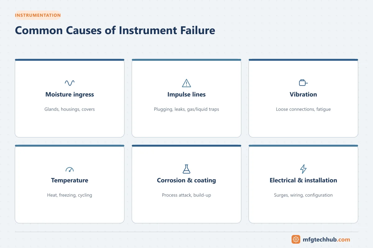
Most instrument failures are not random. They come from a small set of recurring causes: water ingress, blocked impulse lines, vibration, heat, corrosion, electrical disturbances and installation mistakes. Understanding these patterns lets maintenance teams prevent failures instead of repeatedly repairing them.
1. Moisture and water ingress
Water is the leading enemy of field electronics.
How it happens: damaged or wrong cable glands, missing blanking plugs, loose housing covers, condensation inside enclosures, washdown and rain.
Symptoms: erratic readings, earth faults, corrosion on terminals, failed electronics.
Prevention:
- Use correctly sized and rated cable glands, and seal unused entries
- Point cable entries downward or add drip loops
- Tighten housing covers and check O-rings
- Use breather/drain elements where condensation is expected
- Choose enclosures with suitable IP ratings (for example IP66/IP67)
2. Impulse line problems
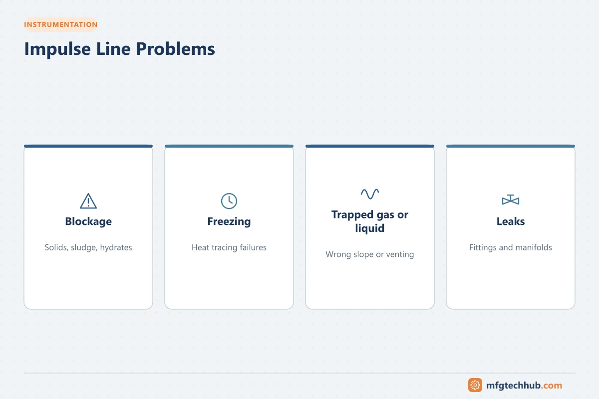
Pressure, DP flow and DP level instruments depend on impulse lines.
| Problem | Cause | Prevention |
|---|---|---|
| Blockage | Solids, crystallization, viscous fluids | Diaphragm seals, purge systems, correct line sizing, regular blowdown |
| Freezing | Water in lines in cold weather | Heat tracing and insulation, with tracing monitoring |
| Trapped gas or liquid | Incorrect slope or mounting | Slope lines correctly; mount transmitters below taps for liquids, above for gases |
| Leaks | Loose fittings, vibration | Quality fittings, supports, periodic leak checks |
3. Vibration
Effects: loosened connections, cracked fittings and impulse lines, fatigue of sensors and electronics, noisy readings.
Prevention: mount instruments on stable structures rather than vibrating pipes, use flexible hoses or capillaries, support impulse lines, and choose vibration-rated instruments.
4. Heat and temperature extremes
Effects: electronics outside their temperature ratings fail early; high temperatures degrade seals and fill fluids.
Prevention: use remote seals or longer impulse lines to distance transmitters from hot processes, fit sun shades, respect ambient temperature ratings, and ensure cabinet cooling works.
5. Corrosion and process attack
Effects: diaphragm failure, sensor damage, thermowell erosion and leaks.
Prevention: select wetted materials for the process (for example 316 stainless steel, Hastelloy, tantalum, PTFE linings), check thermowell wake frequency and erosion, and review material selection when processes change.
6. Coating and build-up
Effects: drifting readings on pH probes, magnetic flowmeter electrodes, radar antennas, capacitance probes and displacers.
Prevention: choose sensor types tolerant of coating, use self-cleaning or purge options, and schedule cleaning based on observed drift.
7. Electrical faults and surges
Causes: lightning and switching surges, poor grounding, ground loops, noise from drives, wrong power supply voltage.
Prevention: surge protection for long field cables, correct shield grounding, cable segregation, and stable, protected loop power supplies. See Surge Protection and Grounding and Earthing Techniques.
8. Installation and configuration errors
Many “failures” are built in at installation:
- Wrong range or units configured in the transmitter or control system
- Square-root extraction applied twice (in transmitter and DCS)
- Incorrect thermocouple type or extension cable
- Flowmeters installed without enough straight pipe, or backwards
- Radar level sensors mounted near nozzles or agitators, creating false echoes
- Transmitters left in test or simulation mode after commissioning
Prevention: use installation checklists, verify configuration during loop checks, and audit configurations periodically.
9. Ageing and wear
Components have finite lives: pH electrodes may last months, electrolytic capacitors in electronics dry out over years, and mechanical parts such as floats, linkages and valve packing wear. Plan replacements based on history and manufacturer guidance.
10. Human factors
- Valves left closed after maintenance (for example manifold equalizing valves)
- Forced values or bypasses not removed
- Instruments damaged by people standing on them or using them as supports
- Incorrect replacement parts
Good work procedures, checklists, labeling and handover communication prevent many of these.
Using failure data
Record every failure with its cause in the maintenance system. Reviewing this data regularly shows:
- Bad actors: individual instruments that fail repeatedly
- Systematic problems: a model, installation detail or process condition behind many failures
- Opportunities to change design standards
Quick prevention checklist
| Area | Check |
|---|---|
| Enclosure | Covers tight, glands sealed, no water inside |
| Process connection | Impulse lines intact, traced and sloped correctly; valves in correct position |
| Mounting | Secure, low vibration, protected from heat and impact |
| Wiring | Terminals tight, shields grounded correctly, no damage |
| Configuration | Range, units, damping and output mode correct |
| Diagnostics | No active alarms or NE 107 maintenance messages |
Key takeaways
- Water ingress, impulse line problems, vibration, heat and corrosion cause most instrument failures.
- Many failures are designed in through poor selection, installation or configuration.
- Record failure causes and eliminate repeat problems at the source.
Related tutorials
Before you apply this in a plant: this article is for education. Always check the current edition of the relevant standards, the manufacturer's documentation for your exact product and version, and your site's procedures. Safety-related work needs qualified personnel. See our editorial policy.