
Motor Condition Monitoring: Techniques to Prevent Motor Failures
On this page
Electric motors are everywhere in a plant, and a failed motor can stop a production line, a cooling system or a critical pump. Motor failures come from bearings, windings, rotors, and connections, and each failure type can be detected early with the right technique. Motor condition monitoring combines electrical and mechanical measurements to find problems while there is still time to plan a repair.
Where motors fail
Industry surveys consistently show that bearings and stator windings account for most induction motor failures, with rotor problems, shaft issues and external causes (such as contamination and supply problems) making up the rest. The exact split varies with motor size and type, but a good program must cover both mechanical and electrical failure modes.
| Failure mode | Typical causes |
|---|---|
| Bearing failure | Poor lubrication, contamination, misalignment, overloading, electrical discharge (bearing currents with VFDs) |
| Stator winding failure | Insulation ageing from heat, moisture, contamination, voltage surges, overloads |
| Rotor problems | Broken rotor bars, cracked end rings, eccentricity |
| Connection problems | Loose terminals, failing contactors |
| Supply problems | Voltage unbalance, harmonics, single phasing |
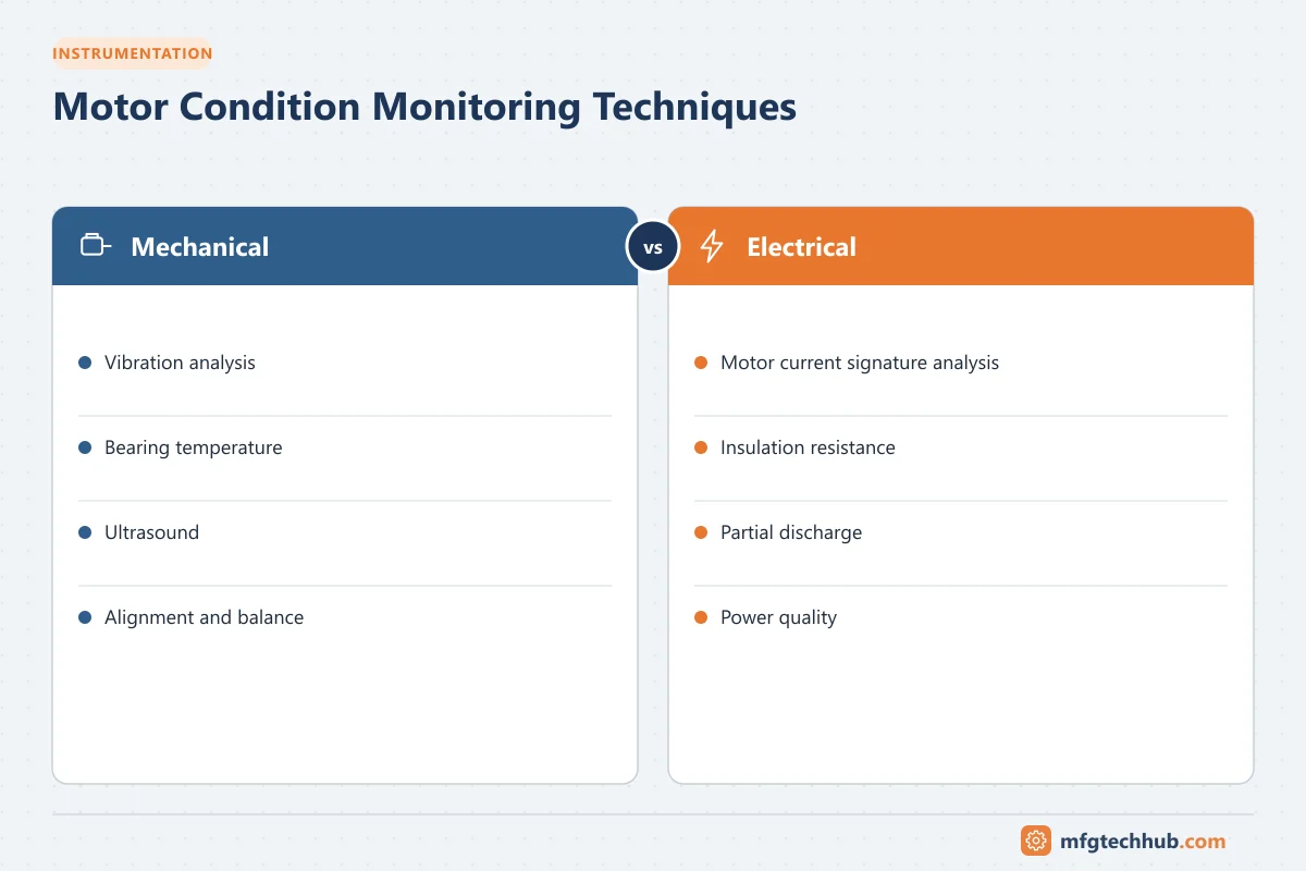
Mechanical techniques
Vibration analysis
Detects bearing defects, unbalance, misalignment, looseness and some electrical problems (such as vibration at twice line frequency). See Vibration Analysis for Rotating Equipment.
Ultrasound
Airborne and structure-borne ultrasound detects early bearing friction and is used to guide condition-based lubrication, applying grease only when needed and stopping when the ultrasound level drops. Over-greasing is a common cause of bearing failure.
Temperature monitoring
- Bearing temperature sensors (RTDs) on larger motors
- Winding temperature sensors (PTC thermistors or RTDs)
- Infrared thermography of motor frames, bearings and terminal boxes
Electrical techniques
Motor current signature analysis (MCSA)
MCSA analyzes the frequency spectrum of the motor supply current, measured with clamp-on current sensors at the MCC. The motor acts as a transducer: mechanical and electrical faults create characteristic frequencies in the current.
A classic example is broken rotor bars, which create sidebands around the supply frequency at:
f = f_supply × (1 ± 2s) where s is slipMCSA can also indicate air-gap eccentricity, some load and mechanical problems, and supply issues. Its main advantage is that measurements are taken safely at the MCC, without access to the motor itself, which is valuable for submerged pumps or motors in hazardous or inaccessible locations.
Insulation resistance and polarization index
Offline tests with an insulation tester measure winding insulation to earth. The polarization index (PI), the ratio of 10-minute to 1-minute insulation resistance, indicates moisture and contamination. IEEE 43 gives recommended minimum values. See Ground Fault Detection and Maintenance.
Surge testing
A surge test applies high-voltage pulses to compare the response of windings and detect turn-to-turn insulation weaknesses that insulation resistance tests cannot find.
Partial discharge (PD) monitoring
For medium-voltage motors (typically 3.3 kV and above), partial discharge in insulation voids and surfaces gradually erodes insulation. Online PD monitoring with sensors at the motor terminals or switchgear trends insulation deterioration while the motor runs.
Power quality and supply monitoring
Voltage unbalance, harmonics and poor voltage regulation cause extra heating. Motor protection relays and power meters can trend supply conditions. A commonly cited guideline (NEMA MG 1) derates motors when voltage unbalance exceeds 1%.
Online motor monitoring
Modern motor protection relays, intelligent MCCs, VFDs and dedicated monitoring sensors provide continuous data:
- Current, voltage, power and power factor
- Thermal capacity used
- Number of starts and running hours
- Winding and bearing temperatures
- Vibration and temperature from wireless or wired sensors
Connecting this data to SCADA, a historian or an IIoT platform allows trending and alarms. See Motor Protection Relays and Wireless Sensor Networks.
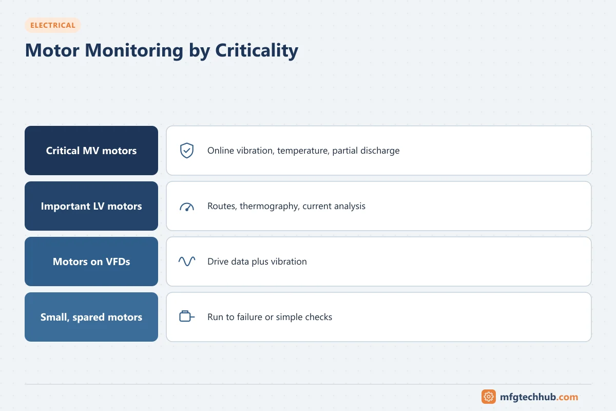
Choosing techniques by motor criticality
| Motor type | Recommended monitoring |
|---|---|
| Small, non-critical, spared motors | Periodic thermography and route vibration, run to failure acceptable |
| Important LV motors | Route or wireless vibration, thermography, periodic insulation tests, MCSA |
| Critical MV motors | Online vibration and temperature, online PD, protection relay data, periodic offline electrical tests |
| Motors on VFDs | Add bearing current checks, shaft grounding inspection and drive diagnostics |
Building the program
- List motors and rank them by criticality.
- Select techniques that cover each motor’s likely failure modes.
- Establish baselines after installation or repair.
- Trend results and set alarm thresholds.
- Combine findings from different techniques for confident diagnosis.
- Feed repair findings back into the program.
Key takeaways
- Bearings and windings cause most motor failures; monitor both mechanical and electrical condition.
- Vibration, ultrasound and temperature cover mechanical faults; MCSA, insulation tests, surge tests and PD cover electrical ones.
- Online data from protection relays, drives and wireless sensors enables continuous monitoring.
- Match techniques to motor criticality.
Related tutorials
Before you apply this in a plant: this article is for education. Always check the current edition of the relevant standards, the manufacturer's documentation for your exact product and version, and your site's procedures. Safety-related work needs qualified personnel. See our editorial policy.