
Pressure Gauges: Bourdon Tube, Diaphragm and Bellows Compared, with Selection and Installation Guidance
On this page
Mechanical pressure gauges are the most common instruments in any plant: on pumps, compressors, filters, vessels and utilities. They need no power, show pressure locally and serve as an independent check on transmitters. Choosing the right element, range and accessories prevents the two classic problems: gauges that are wrong and nobody notices, and gauges that fail dangerously under pulsation or overpressure.
The three main elements
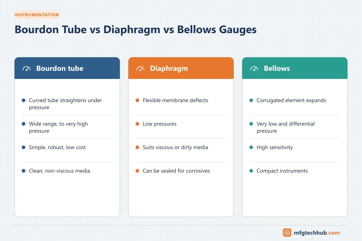
| Element | How it works | Typical range | Strengths | Limitations |
|---|---|---|---|---|
| Bourdon tube | A curved, flattened tube straightens under pressure; movement drives the pointer through a linkage | Medium to very high pressures | Simple, low cost, wide range | Not for very low pressures; sensitive to pulsation and viscous or crystallising media |
| Diaphragm | A flexible disc deflects under pressure | Low to medium pressures | Can be flush and open-port for viscous, dirty or crystallising media; higher overpressure capability | Lower maximum pressure |
| Capsule | Two diaphragms joined at their edges | Very low pressures (mbar range) | Very sensitive, for gases | Gases only, low overpressure |
| Bellows | A corrugated tube expands and contracts | Low pressures and differential pressure | Large movement, sensitive | Fatigue under pulsation; larger |
Differential pressure gauges often use two diaphragms or a piston-and-magnet design, for example for filter monitoring.
Standards and accuracy classes
EN 837 covers Bourdon tube gauges (Part 1) and diaphragm and capsule gauges (Part 3), with accuracy classes expressed as a percentage of span (for example class 1.0 = ±1 % of span). In North America, ASME B40.100 defines accuracy grades. Precision test gauges have tighter classes. See Key Standards.
Selecting a gauge
| Parameter | Guidance |
|---|---|
| Range | Normal working pressure typically in the middle part of the scale (often around half to two-thirds of full scale); avoid continuous operation near full scale |
| Accuracy class | Indication only: general classes; critical or test gauges: finer classes |
| Dial size | Readable from the operator’s normal position |
| Wetted materials | Compatible with the medium (stainless steel for most process uses) |
| Case and filling | Liquid filling (glycerine or silicone) dampens pulsation and vibration |
| Connection | Bottom or back, thread type matching the installation |
| Safety pattern | Solid front and blow-out back for high pressures, especially gases |
| Reference | Gauge, absolute or compound (vacuum and pressure); see Pressure References |
Accessories that solve common problems
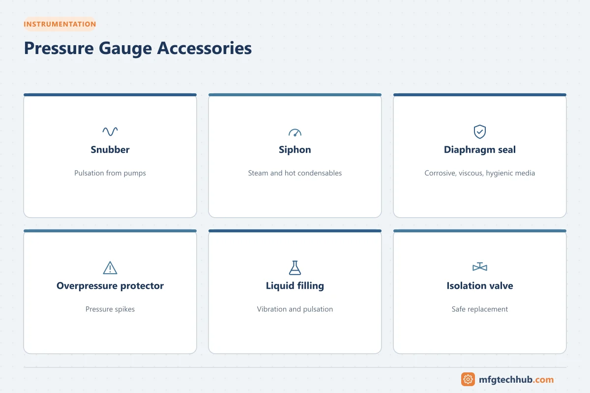
| Problem | Accessory |
|---|---|
| Pulsation (reciprocating pumps, compressors) | Snubber or restrictor, liquid-filled gauge |
| Steam and hot condensable media | Siphon (pigtail) to keep hot steam away from the element |
| Corrosive, viscous, crystallising or hygienic media | Diaphragm seal (chemical seal), possibly with capillary |
| Overpressure spikes | Overpressure protector or higher-range gauge |
| Maintenance without shutdown | Isolation valve or gauge manifold with vent |
Installation
- Mount with an isolation valve so the gauge can be changed safely; vent before removal.
- Mount vertically unless the gauge is designed for another position.
- Protect from vibration: mount remotely with a flexible line or use a liquid-filled gauge.
- For steam, fill the siphon with water before commissioning.
- Keep the vent or blow-out back clear.
Checking and calibration
- Compare with a reference gauge or pressure calibrator at several points, rising and falling, to catch hysteresis.
- Record as-found and as-left results; adjust or replace.
- In service, a gauge that does not return to zero after depressurising or a bent pointer are signs to replace it.
See Calibration and Traceability and Loop Calibrators.
Common failures
| Symptom | Likely cause | Remedy |
|---|---|---|
| Pointer vibrates or wears quickly | Pulsation or vibration | Snubber, liquid filling, remote mounting |
| Does not return to zero | Overpressure has deformed the element | Replace; add overpressure protection |
| Reading sluggish | Blocked port or snubber | Clean; use diaphragm seal |
| Fogged dial or liquid leaks | Seal failure | Replace |
| Burst or leak | Corrosion, fatigue, wrong material | Correct materials, safety pattern case |
Frequently asked questions
What is the difference between a Bourdon tube and a diaphragm gauge?
A Bourdon tube gauge uses a curved tube that straightens under pressure and suits medium to very high pressures. A diaphragm gauge uses a flexible disc and suits low pressures and viscous, dirty or corrosive media, especially with an open, flush connection.
Why are pressure gauges filled with liquid?
Liquid filling (usually glycerine or silicone oil) dampens pointer movement caused by pulsation and vibration, making the gauge readable and extending its life.
What range should a pressure gauge have?
Normally so that the working pressure is in the middle part of the scale, avoiding continuous operation near full scale and leaving margin for pressure peaks.
Key takeaways
- Bourdon tubes for medium to high pressures, diaphragms and capsules for low pressures and difficult media, bellows for low and differential pressures.
- Choose the range so normal pressure sits mid-scale.
- Use snubbers, siphons, seals and overpressure protection for difficult services.
- Check gauges regularly and replace those that are damaged or out of tolerance.
Related tutorials
Before you apply this in a plant: this article is for education. Always check the current edition of the relevant standards, the manufacturer's documentation for your exact product and version, and your site's procedures. Safety-related work needs qualified personnel. See our editorial policy.