
Grounding and Earthing Techniques for Industrial Safety and Instrumentation
On this page
Grounding (earthing) does two jobs in an industrial plant. Safety earthing makes sure a fault in equipment trips protection quickly and does not leave metal parts at a dangerous voltage. Functional or instrument earthing gives electronic systems a stable reference and a path for interference, so signals stay clean. Many plant problems, from electric shock risks to noisy 4-20 mA signals and communication errors, trace back to poor grounding.
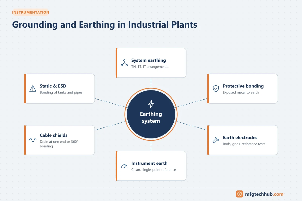
“Grounding” is the common North American term and “earthing” the IEC/British term; they mean the same thing.
System earthing arrangements (IEC 60364)
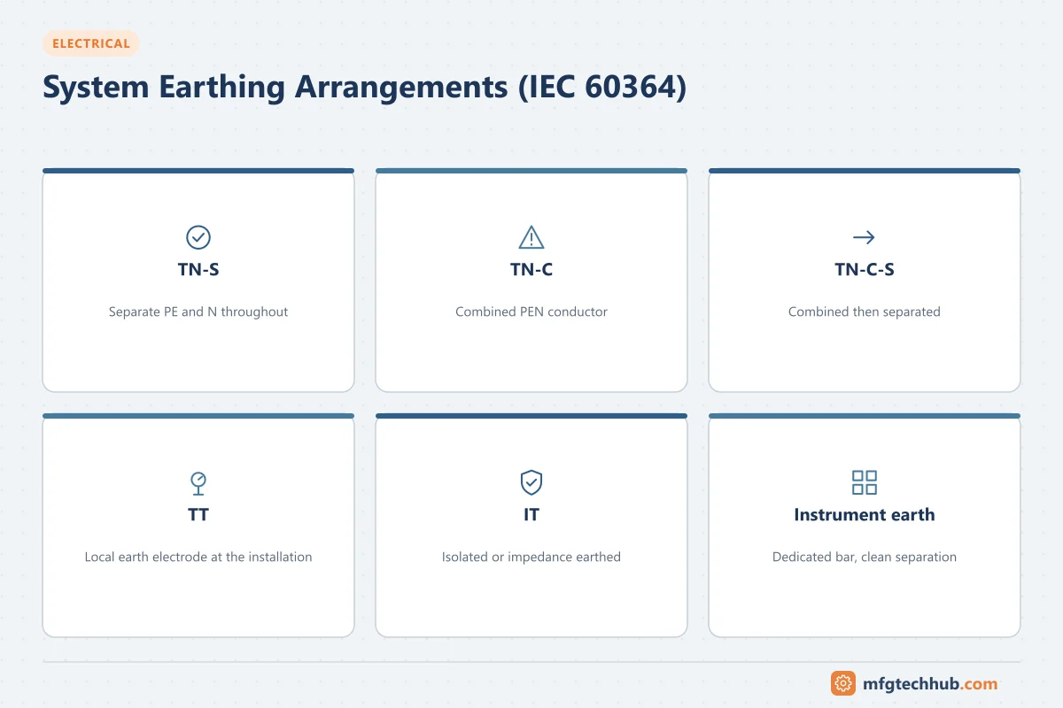
The earthing system describes how the supply source and the equipment are connected to earth. The letters mean: first letter, the source (T = directly earthed, I = isolated or earthed through an impedance); second letter, the equipment (T = earthed locally, N = connected to the source neutral).
| System | Description | Characteristics |
|---|---|---|
| TN-S | Separate neutral (N) and protective earth (PE) conductors throughout | Clean earth; preferred for installations with electronics |
| TN-C | Combined neutral and protective conductor (PEN) | Not recommended for electronic installations; neutral currents flow in earthed metalwork |
| TN-C-S | Combined PEN in the supply, separated at the installation | Common utility supply arrangement |
| TT | Source earthed; equipment earthed by a separate local electrode | High fault loop impedance, so RCDs are usually needed |
| IT | Source isolated or high-impedance earthed | First fault does not trip; used where continuity is critical (some process plants, hospitals); requires insulation monitoring |
Protective earthing and bonding
- Protective earth (PE) conductors connect exposed metal parts of equipment to the earthing system, so a fault to the enclosure causes a fault current large enough to trip the protective device.
- Main equipotential bonding connects incoming metallic services (water, gas pipes, structural steel) to the main earthing terminal.
- Supplementary bonding connects simultaneously accessible metal parts in specific locations.
Bonding keeps all touchable metal at nearly the same potential, which is what protects people.
Earth electrodes and earth resistance
The earth termination system connects the installation to the general mass of earth, using:
- Driven rods (copper-bonded steel)
- Horizontal tapes or conductors buried in trenches
- Earth grids or meshes, especially in substations
- Foundation earth electrodes using building reinforcement
Required resistance values depend on the application and local regulations, and on the design of the whole protection system. Substation grids are designed so that touch and step voltages during faults stay within safe limits (IEEE 80 is the key design standard).
Testing earth resistance
- Fall-of-potential method (three-point test): uses temporary test spikes; the standard method for electrodes.
- Clamp-on (stakeless) testing: measures electrodes in a multi-grounded system without disconnection; convenient but only valid in suitable configurations.
- Soil resistivity testing (Wenner method): used during design.
Test periodically, preferably in dry conditions, and after construction work nearby.
Instrument and control system earthing
Electronic systems need a low-noise reference. Typical practice:
- Dedicated instrument earth bar in control and marshalling cabinets, connected to the plant earthing system at a single defined point
- Separation within the cabinet between protective earth (PE) and instrument (signal) earth bars, joined as specified by the control system vendor
- Intrinsically safe (IS) earth for barriers, meeting the requirements of hazardous area standards
- Following the control system vendor’s earthing guidelines, which often specify conductor sizes and connection points
Older designs sometimes used a completely separate “clean earth” electrode. This can create dangerous potential differences during faults and is generally discouraged; instrument earths should be connected to the main earthing system in a controlled way.
Grounding cable shields
Screened cables protect signals from electrical noise, but the shield must be grounded correctly:
| Signal type | Common practice |
|---|---|
| Analog 4-20 mA and low-level signals | Ground the shield at one end only, usually the control room end, to avoid ground loops |
| Thermocouples and RTDs | Single-point grounding, following the transmitter or system guidance |
| High-frequency digital (Ethernet, fieldbus, VFD motor cables) | Ground at both ends with 360° terminations, combined with good equipotential bonding |
A ground loop occurs when a shield or signal is grounded at two points with different potentials; current flows in the shield and creates noise. Isolated inputs and signal isolators also help break ground loops.
Static electricity and ESD
In plants handling flammable liquids, powders or solvents, static bonding and grounding of tanks, piping, drums, hoses and road tankers prevents static discharges that could ignite flammable atmospheres. Grounding clamps with monitoring (interlocked with loading pumps) are common.
Common grounding problems
| Symptom | Possible grounding cause |
|---|---|
| Noisy or drifting 4-20 mA signals | Shield grounded at both ends, ground loops, shared earth return with power circuits |
| Communication errors | Poor bonding between cabinets, incorrect shield terminations |
| RCD nuisance tripping | Neutral-to-earth connections downstream of the RCD |
| Shocks from equipment | Missing or broken protective earth |
| Repeated surge damage | High-impedance earth, long bonding connections |
Key takeaways
- Safety earthing and bonding protect people; functional earthing protects signal quality.
- TN-S, TT and IT systems behave differently in faults and need different protection.
- Test earth electrodes periodically using proper methods.
- Ground analog signal shields at one point, and high-frequency cable shields at both ends with good bonding.
Related tutorials
Before you apply this in a plant: this article is for education. Always check the current edition of the relevant standards, the manufacturer's documentation for your exact product and version, and your site's procedures. Safety-related work needs qualified personnel. See our editorial policy.