
Torque Sensors for Motor and Drive Applications
On this page
Torque is the twisting force that makes a shaft turn. Measuring it tells you how hard a motor is working, how much power is being delivered to a pump or conveyor, and whether a gearbox, coupling or process load is behaving normally. Torque sensors are used on motor test benches, in drive commissioning, in tightening tools, and increasingly for condition monitoring of critical machines.
This article explains how torque sensors work, the main types, how to select and install them, and how torque data is used in motor and drive applications.
Torque, speed and power
Torque (T) is measured in newton-metres (N·m). Combined with rotational speed, it gives mechanical power:
P (W) = T (N·m) × ω (rad/s) = T × 2π × n / 60      (n in rpm)
P (kW) ≈ T (N·m) × n (rpm) ÷ 9549
Example: a motor delivering 95.5 N·m at 1,500 rpm produces about 95.5 × 1,500 ÷ 9,549 ≈ 15 kW of shaft power.
Because electrical input power is easy to measure, comparing it with measured shaft power gives the true efficiency of a motor, drive or gearbox.
Rotary vs reaction torque sensors
| Type | What it measures | Typical use |
|---|---|---|
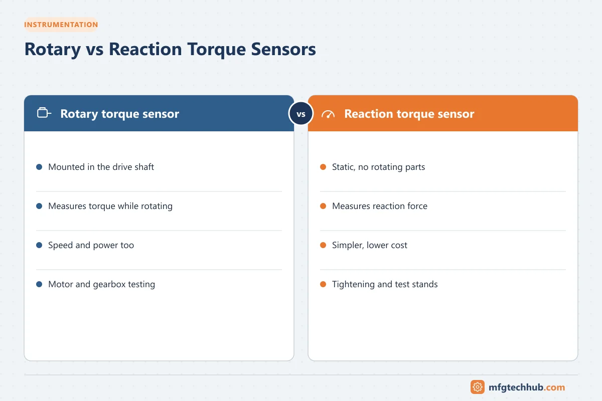
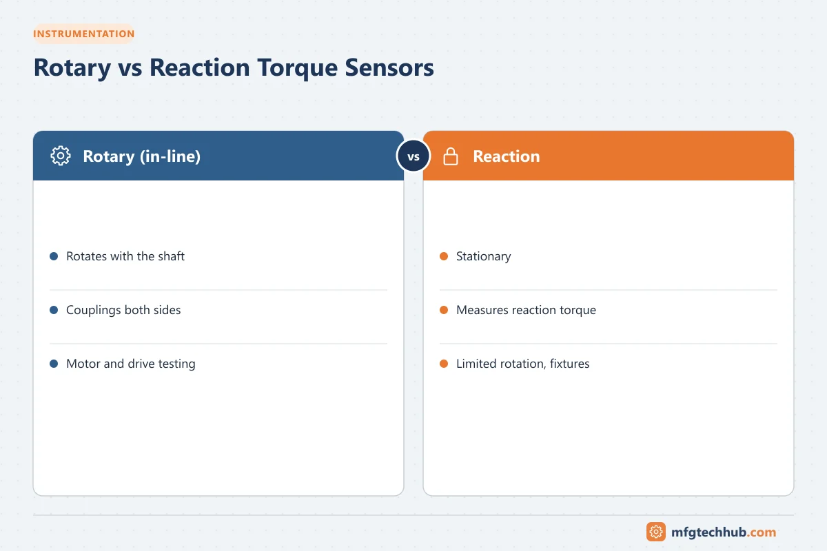
| Rotary (in-line) torque sensor | Torque in a rotating shaft, installed between driver and load | Motor and gearbox testing, dynamometers, pump and fan efficiency tests |
| Reaction torque sensor | Torque on a stationary part that resists rotation | Screw-tightening stations, viscosity measurement, small motor testing, torque calibration |
Reaction sensors are simpler and cheaper because nothing rotates. Rotary sensors must transfer the signal from a spinning shaft, which adds cost and complexity.
How torque sensors work
Strain gauge torque sensors
Most torque sensors use strain gauges bonded to a precisely machined shaft or flexure. When torque twists the shaft, the surface experiences shear strain at 45° to the axis. Four gauges arranged in a Wheatstone bridge convert this strain into a small voltage while compensating for temperature and bending.
On a rotary sensor, the bridge signal must cross from the rotating shaft to the stationary housing. Older designs used slip rings, which wear and add noise. Modern designs use contactless telemetry, with inductive or radio power and digital signal transmission, which allows higher speeds and much longer life.
Magnetoelastic sensors
Magnetoelastic sensors measure how torque changes the magnetic properties of a ferromagnetic shaft. They are non-contact and can sometimes be built directly into an existing shaft, which makes them attractive for embedding in drivetrains and products.
Surface acoustic wave (SAW) sensors
SAW sensors use tiny resonators on the shaft whose frequency changes with strain. They are read wirelessly and suit compact, high-volume applications.
Indirect torque estimation
Variable frequency drives (VFDs) estimate motor torque from measured current and a motor model, and many display it continuously. This is good enough for monitoring trends and protecting equipment, but it is less accurate than a direct measurement, especially at low speed or with a poorly tuned motor model. See VFDs and soft starters.
Key specifications
| Specification | What it means |
|---|---|
| Rated (nominal) torque | Full-scale range, for example 50 N·m or 5 kN·m |
| Accuracy class | Often 0.05% to 0.5% of full scale for quality sensors |
| Maximum speed | Upper speed limit for rotary sensors, which can exceed 20,000 rpm |
| Overload and breaking torque | Safe overload (often 150-200%) and the point of mechanical failure |
| Torsional stiffness | How much the sensor twists; affects the dynamics of the drivetrain |
| Output | mV/V bridge, ±10 V, 4-20 mA, frequency, or digital (for example EtherCAT or CAN) |
| Speed/angle measurement | Many rotary sensors include an encoder for speed and power calculation |
Selecting a torque sensor
- Size for the real peak torque, not the average. Motor starting, direct-on-line starts and shock loads can reach several times rated torque.
- Keep the working range in the upper part of the scale. A sensor running at 5% of full scale gives poor resolution.
- Check speed and dynamic response for the application, especially for fast transients.
- Consider stiffness. A soft sensor can change the natural frequency of the drivetrain and cause resonance.
- Choose the right output for your data acquisition system or PLC.
Installation best practices
- Use flexible couplings on both sides of an in-line sensor so that misalignment and bending loads do not reach the measuring element.
- Align shafts carefully, following the manufacturer’s tolerance for angular and parallel offset.
- Support the sensor housing so it cannot rotate, but do not clamp it rigidly in a way that introduces side loads.
- Guard all rotating parts and follow machine safety rules.
- Zero the sensor with no load before tests, and follow warm-up recommendations.
Applications in motors and drives
Motor and drive testing
Test benches (dynamometers) use a torque sensor between the motor under test and a load machine to produce torque-speed curves, measure efficiency and verify performance against motor standards.
Pump, fan and compressor efficiency
Measuring shaft torque and speed on site gives the actual power absorbed by the machine. Compared with flow and head measurements, this shows the machine’s operating efficiency and whether it is running far from its best efficiency point.
Gearbox and drivetrain monitoring
Torque ripple and sudden torque peaks can reveal gear damage, coupling problems or process blockages. Torque monitoring is used on critical equipment such as extruders, mixers and wind turbine drivetrains.
Tightening and assembly
Reaction and rotary sensors in assembly tools verify that bolts and screws reach the specified torque, often recording each result for traceability.
Calibration
Torque sensors are calibrated by applying known torques, usually using precision lever arms and dead weights or a reference torque transducer. Standards such as DIN 51309 and EN ISO 6789 (for hand torque tools) define calibration procedures. Calibrate at regular intervals and after any overload event.
Common problems
| Symptom | Likely cause |
|---|---|
| Zero drift | Temperature changes, missing warm-up, damaged gauges after overload |
| Noisy or spiky reading | Misalignment, vibration, electrical noise on unshielded cables |
| Reading differs from drive estimate | Motor model error in the drive, mechanical losses between sensor and motor |
| Periodic torque ripple | Misalignment, coupling wear, gear tooth damage, cogging |
Key takeaways
- Torque multiplied by speed gives mechanical power, which is essential for efficiency measurement.
- Rotary sensors measure torque in spinning shafts; reaction sensors measure it on stationary parts.
- Strain gauge sensors with contactless telemetry are the industrial workhorse.
- Correct sizing, alignment and flexible couplings matter as much as sensor accuracy.
Related tutorials
Before you apply this in a plant: this article is for education. Always check the current edition of the relevant standards, the manufacturer's documentation for your exact product and version, and your site's procedures. Safety-related work needs qualified personnel. See our editorial policy.