
Pressure Transmitters: Working, Types, Selection, Installation, Calibration and Troubleshooting
On this page
A pressure transmitter measures the pressure of a gas, liquid or steam and converts it into a standard signal (usually 4–20 mA with HART, or a digital fieldbus) for a PLC or DCS. Pressure is the most common process measurement, and pressure transmitters are also used to measure level and flow through differential pressure.
This guide covers how they work, how to select one for a specific application, and how to install, calibrate and troubleshoot them.
How a pressure transmitter works
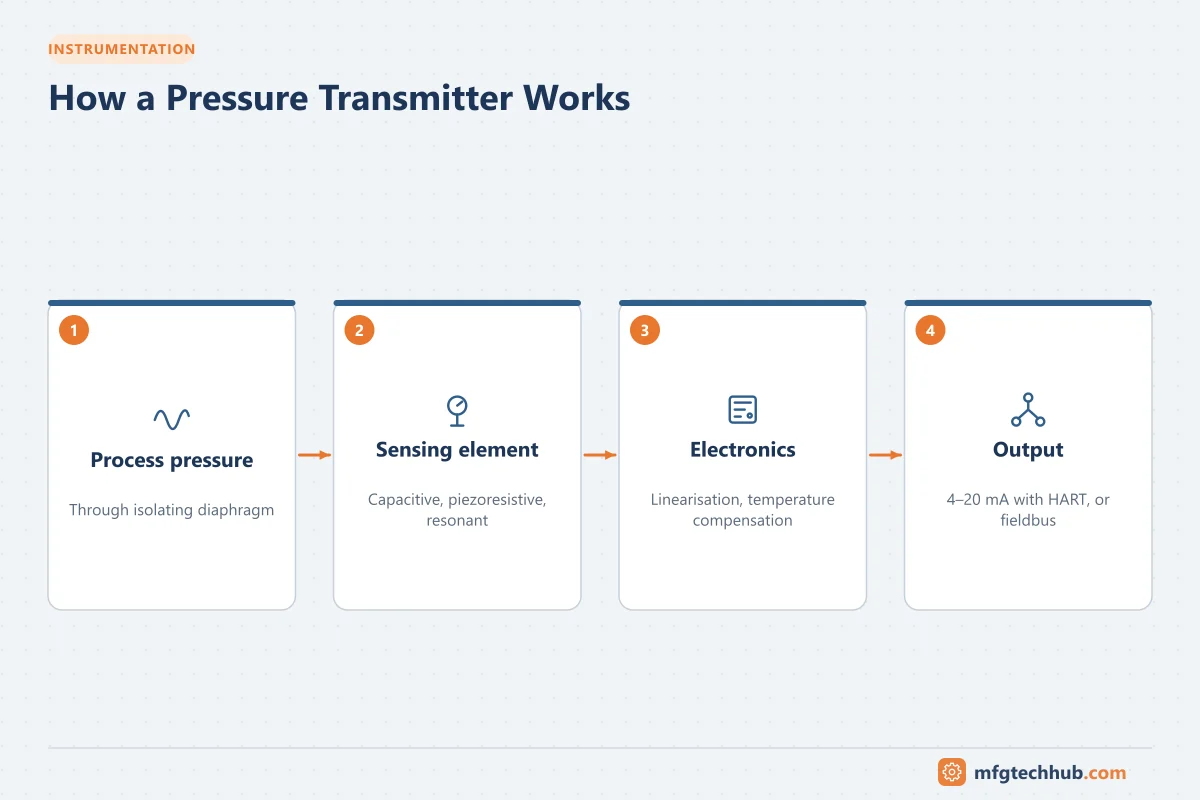
- Process connection and diaphragm: the process pressure acts on an isolating diaphragm, usually through a fill fluid, or directly on the sensor.
- Sensor: converts pressure into an electrical change.
- Electronics: linearise, compensate for temperature and static pressure, apply the configured range and damping.
- Output: 4–20 mA (often with HART), or FOUNDATION Fieldbus, PROFIBUS PA, Ethernet-APL or wireless. See HART Protocol Explained.
Sensor technologies
| Technology | Principle | Typical use |
|---|---|---|
| Capacitive | Diaphragm movement changes capacitance between plates | Widely used in process DP and pressure transmitters; good at low ranges |
| Piezoresistive (silicon) | Pressure changes the resistance of a silicon element | Very common in industrial and compact transmitters |
| Strain gauge (thin film / bonded) | Resistance change of a gauge on a deforming element | High pressures, hydraulics, compact sensors |
| Resonant | Pressure changes the resonant frequency of a silicon element | High-stability process transmitters |
| Piezoelectric | Charge generated by dynamic stress | Dynamic and pulsating pressure; not for static pressure |
See also Manometers vs Piezoelectric Sensors.
Types by pressure reference
| Type | Measures | Typical applications |
|---|---|---|
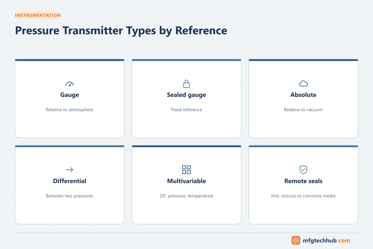
| Gauge (G) | Pressure relative to atmosphere | Pump discharge, compressed air, open tanks, hydraulics |
| Sealed gauge | Relative to a sealed reference (roughly atmospheric) | High-pressure or washdown applications where venting is difficult |
| Absolute (A) | Relative to vacuum | Vacuum distillation, vapour pressure, barometric compensation |
| Differential (DP) | Difference between two pressures | Flow across orifices, level in tanks, filter and heat-exchanger fouling |
| Multivariable | DP plus static pressure and temperature | Compensated gas and steam flow |
Level and flow with DP: see Float, Displacer and DP Level, DP Flowmeters and the DP level calculator.
Remote (diaphragm) seals
A remote seal isolates the transmitter from the process with a diaphragm connected by a filled capillary. Use seals for corrosive, viscous, crystallising, hygienic, very hot or slurry services, or where impulse lines would plug.
Trade-offs: slower response (long capillaries), temperature errors from fill-fluid expansion, and head effects from the capillary height. Keep capillaries short and symmetric in DP applications, choose fill fluids suitable for the temperature and vacuum, and consider direct-mount or electronic remote sensor designs.
Understanding accuracy specifications
Datasheet “accuracy” is usually reference accuracy at laboratory conditions, stated as a percentage of calibrated span. Real installed performance also includes:
- Ambient temperature effect (changes in electronics and sensor with temperature)
- Static pressure effect (for DP transmitters at high line pressure)
- Long-term stability (drift over years)
- Installation effects (mounting position, seals, impulse lines)
Manufacturers often provide a total probable error (TPE), typically combining these effects as a root-sum-square. Compare transmitters on total performance at your conditions, not on reference accuracy alone.
Turndown: the ratio of the upper range limit (URL) to the calibrated span. A transmitter with URL 100 bar calibrated 0–10 bar has a turndown of 10:1. Accuracy usually degrades at higher turndowns, so choose a sensor range close to the application.
How to select a pressure transmitter: step by step
| Step | Question | Guidance |
|---|---|---|
| 1. Measurement type | Gauge, absolute, differential or multivariable? | Vacuum and vapour pressure need absolute; flow/level/filters need DP |
| 2. Process medium | Gas, liquid, steam, slurry, corrosive, hygienic? | Drives wetted materials, seals and installation |
| 3. Range | Normal, minimum and maximum pressure; overpressure; vacuum? | Normal value ideally in the middle of the span; check maximum working pressure and overpressure limits |
| 4. Temperature | Process and ambient temperature ranges | Remote seals or heat dissipation for hot processes; check electronics limits |
| 5. Accuracy and stability | What total error is acceptable? How often can you calibrate? | Use TPE at operating conditions; better stability allows longer calibration intervals |
| 6. Wetted materials | Compatible with the chemistry? | 316L stainless steel is common; alloy C-276, Monel, tantalum and others for corrosive services; gold-plated diaphragms can reduce hydrogen permeation |
| 7. Diaphragm and fill fluid | Hygienic? Vacuum? High temperature? Oxygen service? | Fill fluids must suit temperature and vacuum; special cleaning and fills for oxygen and hygienic service |
| 8. Process connection | Threaded, flanged, hygienic clamp, remote seal? | Match piping standards and cleaning requirements |
| 9. Environment | Outdoor, washdown, vibration, corrosive atmosphere? | Enclosure rating (for example IP66/IP67, NEMA 4X), housing material, mounting |
| 10. Hazardous area | Zone/Division and gas group? | Intrinsically safe (Ex i) or flameproof (Ex d) certification to ATEX, IECEx or North American schemes as applicable |
| 11. Safety function | Will it be part of a SIF? | Devices with IEC 61508 certification or proven-in-use justification, safety manual, FMEDA data. See Functional Safety |
| 12. Output and protocol | 4–20 mA/HART, fieldbus, Ethernet-APL, wireless? | Match the control system and asset management strategy |
| 13. Diagnostics | Needed for maintenance strategy? | Plugged impulse line detection, NAMUR NE 107 status, sensor health |
| 14. Response time | Fast pressure changes, surge, compressor control? | Check response time and damping; avoid long capillaries |
| 15. Maintainability and lifecycle | Standardisation, spares, local support, calibration interval? | Limit the number of models in a plant; consider total cost of ownership |
Example specification
Service: pump discharge, cooling water, normal 6 bar(g), maximum 10 bar(g), 35 °C, outdoor, non-hazardous area.
Selection: gauge transmitter, sensor range around 0–16 or 0–20 bar calibrated 0–10 bar(g); 316L wetted parts; 1/2“ NPT process connection with a 2-valve manifold; IP66/IP67 housing; 4–20 mA with HART; damping set to filter pump pulsation.
Installation best practices
Impulse lines
| Medium | Tap position | Transmitter position | Why |
|---|---|---|---|
| Liquid | Side of the pipe (not top or bottom) | Below the taps | Gas bubbles rise back to the pipe; lines stay full of liquid |
| Gas | Top or side of the pipe | Above the taps | Condensate drains back to the pipe |
| Steam | Side of the pipe | Below the taps, with condensate-filled lines | Protects the transmitter from live steam temperature |
- Keep impulse lines short, with a continuous slope (often specified around 1:10 to 1:12) and no high or low pockets.
- For DP, keep both legs at the same temperature and similar routing to avoid density errors.
- Use heat tracing where liquids can freeze or become viscous, without overheating the transmitter.
- Use snubbers or damping for pulsating pressures; avoid mounting on vibrating equipment.
Manifolds
| Manifold | Use |
|---|---|
| 2-valve | Gauge/absolute transmitters: isolation and vent/test |
| 3-valve | DP transmitters: two isolation valves and an equalising valve |
| 5-valve | DP transmitters with additional vent/test valves, common in gas and steam |
Correct DP valve sequence (to avoid over-ranging the sensor on one side): when isolating, open equalising first, then close block valves; when returning to service, open one block valve, close equalising, then open the other block valve. Follow your site procedure.
Electrical
- Correct loop supply voltage and total loop resistance (including HART resistor).
- Shielded twisted pair, shield grounded according to site practice (commonly at one end).
- Cable glands and entries that maintain the enclosure and hazardous-area rating.
Calibration and verification
- As-found test at several points (for example 0, 25, 50, 75 and 100 % of span, rising and falling).
- Compare errors with the tolerance defined for the loop.
- If out of tolerance, adjust:
- Sensor (digital) trim: corrects the digital reading against the reference.
- Analog output (D/A) trim: corrects the 4–20 mA output against a precision meter.
- Re-ranging (LRV/URV) changes the span; it is not a calibration.
- As-left test and documentation.
Use a pressure calibrator or dead-weight tester with suitable accuracy (commonly several times better than the device under test), and a loop calibrator for the output. See Calibration and Standardization and Loop Calibrators.
Zero checks in place: for DP transmitters, equalise the manifold and check zero. For wet-leg level applications, account for the leg’s hydrostatic head.
Commissioning checklist
- Tag, range, units, damping and transfer function configured and matching the control system
- Transmitter and control system scaling identical
- Impulse lines leak-tested, filled or vented as required
- Zero checked at process conditions where possible
- Loop check: simulate 4, 12 and 20 mA and confirm values and alarms in the control system
- Failure mode (upscale/downscale, NAMUR NE 43 levels) set and alarmed. See the 4–20 mA calculator
- Documentation and calibration records completed
Troubleshooting
| Symptom | Likely causes | Checks |
|---|---|---|
| Reading stuck | Plugged impulse line or tap, closed isolation valve, frozen line, output fixed (loop test mode) | Valve positions, blow down lines (safely), check heat tracing, HART status |
| Reading drifts slowly | Sensor drift, fill-fluid leak in seal, temperature effect | As-found test, compare with a reference gauge |
| Constant offset | Wrong zero, wet leg changed, mounting position effect | Zero with equalised manifold; check leg fill |
| Noisy reading | Pulsation, vibration, electrical noise, gas in liquid lines | Damping, snubber, vent lines, cable and grounding |
| DP flow reads high/low | Leak in one leg, unequal leg temperatures, wrong density assumptions | Leak test, leg routing, configuration |
| Output at 3.6 or 21+ mA | Transmitter detected a fault (NE 43 alarm levels) | HART diagnostics |
| Analog and digital values differ | Range mismatch, D/A trim needed, loop resistance problem | Compare LRV/URV, perform output trim, measure loop current |
See Instrument Troubleshooting for the general method.
Frequently asked questions
What is the difference between a pressure sensor and a pressure transmitter?
A sensor converts pressure into a raw electrical signal. A transmitter includes the sensor plus electronics that compensate, scale and transmit a standard signal (such as 4–20 mA with HART) over long distances to a control system.
How do I choose the pressure range?
Choose a transmitter whose sensor range covers the maximum expected pressure with margin, and calibrate the span so the normal operating value is well inside it. Avoid very high turndowns, which reduce accuracy.
Should a transmitter be mounted above or below the pipe?
For liquids and steam, below the taps so the lines stay liquid-filled; for gas, above the taps so condensate drains back into the pipe.
Key takeaways
- Choose gauge, absolute or DP based on the measurement, then range, materials, environment and certifications.
- Compare total performance at operating conditions, not just reference accuracy.
- Installation (impulse lines, manifolds, seals) decides real-world accuracy and reliability.
- Calibrate with as-found/as-left records and use HART diagnostics for troubleshooting.
Related tutorials
Before you apply this in a plant: this article is for education. Always check the current edition of the relevant standards, the manufacturer's documentation for your exact product and version, and your site's procedures. Safety-related work needs qualified personnel. See our editorial policy.