
What Is a P&ID? Piping and Instrumentation Diagrams Explained
On this page
A Piping and Instrumentation Diagram (P&ID) is the master drawing of a process plant. It shows every item of process equipment, the pipes that connect them, and every instrument, control loop, valve and safety device needed to operate the process. If you work in instrumentation, control, process or maintenance engineering, the P&ID is the drawing you will use most.
This article explains what a P&ID contains, who uses it, how it evolves during a project, and why keeping it accurate is so important.
What a P&ID shows
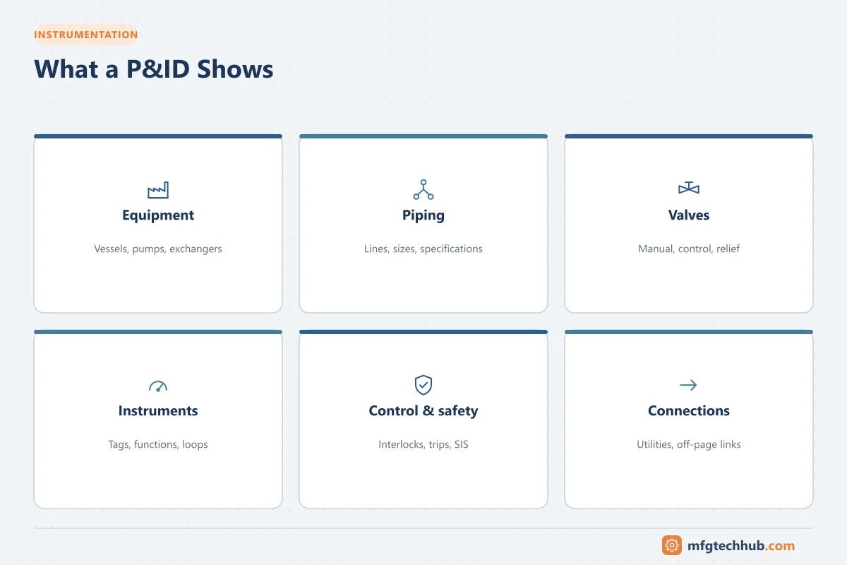
A P&ID is a schematic, not a scale drawing. It shows how things are connected functionally, not where they are physically located. A typical P&ID includes:
- Process equipment: vessels, tanks, pumps, compressors, heat exchangers, columns, filters, with their tag numbers
- Piping: all process lines, with line numbers, sizes, pipe specifications and insulation or tracing requirements
- Valves: manual valves, control valves, check valves, relief valves, with sizes and types
- Instrumentation: transmitters, gauges, switches, analyzers and their connections, identified with ISA tag numbers
- Control and signals: control loops, interlocks, and the signal types connecting instruments to the control system
- Safety devices: pressure safety valves, rupture discs, safety instrumented functions and alarms
- Interfaces: off-page connectors to other P&IDs, utility connections, vendor package boundaries
A P&ID usually does not show exact pipe routing, physical dimensions, electrical power wiring, or detailed control logic, which are covered by other documents.
P&ID vs other plant documents
| Document | Purpose |
|---|---|
| Process Flow Diagram (PFD) | Overall process flow, major equipment and design conditions (flows, temperatures, pressures) |
| P&ID | Complete functional detail of piping, equipment, instruments and control |
| Instrument loop diagram | Wiring and connection details of each individual loop (ISA-5.4) |
| Cause-and-effect / logic diagrams | What each interlock or trip does |
| Isometric drawings | Physical pipe routing for fabrication |
See P&ID vs PFD: Differences and Use Cases for a detailed comparison.
Who uses P&IDs
- Process engineers design the process and control philosophy.
- Instrumentation and control engineers specify instruments, control loops, alarms and interlocks, and configure the PLC or DCS from the P&ID.
- Piping and mechanical engineers design lines and equipment to match.
- Safety teams use P&IDs as the basis for HAZOP studies and other process hazard analyses.
- Operators learn the process and use P&IDs for isolation, startup and troubleshooting.
- Maintenance teams plan isolations, lockout/tagout and repairs.
- Project and procurement teams extract equipment, valve and instrument lists.
How a P&ID develops during a project
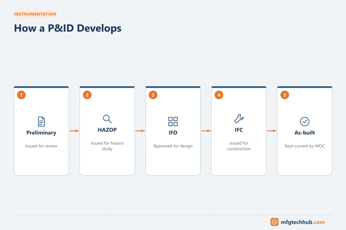
P&IDs go through several revisions as the design matures:
- Preliminary / “issued for review”: based on the PFD, showing main equipment, lines and control concepts.
- Issued for HAZOP: detailed enough for the hazard study team to examine each line and node.
- Issued for design (IFD) / approved for design: incorporating HAZOP actions and vendor information; used for detailed engineering.
- Issued for construction (IFC): the version used to build the plant.
- As-built: updated to match what was actually installed and commissioned.
Each revision is tracked in the title block, with revision clouds or triangles marking changes.
Why P&ID accuracy matters
An inaccurate P&ID is a safety risk. Operators and maintenance staff rely on it to isolate equipment, find relief paths and understand interlocks. Many industrial incidents have involved modifications that were never reflected in drawings.
Good practice includes:
- Management of Change (MOC): every plant modification must update the P&IDs.
- Regular field verification: walking the lines to check that drawings match reality.
- Controlled document systems: only the current approved revision is available for use.
- Intelligent P&IDs: database-driven software keeps drawings consistent with instrument and equipment lists. See P&ID software tools.
Reading your first P&ID
If you are new to P&IDs, start with these steps:
- Read the legend sheets first; every project defines its own symbols and abbreviations.
- Identify the main equipment and follow the main process flow from feed to product.
- Trace control loops: find the transmitter, controller and control valve with the same loop number.
- Look for safety devices: relief valves, high-high and low-low trips, and emergency shutdown valves.
- Follow off-page connectors to understand how this sheet links to the rest of the plant.
The next articles explain the symbols and line types and how to read instrument loops in detail.
Key takeaways
- A P&ID is the functional master drawing of a process plant, showing equipment, piping, instruments and control.
- It is used by nearly every discipline, from design and HAZOP to operations and maintenance.
- P&IDs evolve through defined revisions and must be kept as-built through management of change.
- Always start reading a P&ID with its legend sheets.
Related tutorials
Before you apply this in a plant: this article is for education. Always check the current edition of the relevant standards, the manufacturer's documentation for your exact product and version, and your site's procedures. Safety-related work needs qualified personnel. See our editorial policy.