
High Voltage Transmission and Step-Down Transformers for Industry
On this page
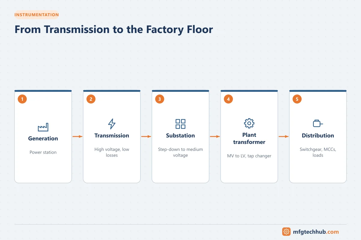
Electricity travels from power stations to factories at high voltage, then passes through several step-down transformers before reaching motors and control panels. Understanding this chain helps engineers read single-line diagrams, specify transformers, and understand fault levels, voltage regulation and losses in their plant.
Why transmit at high voltage?
For the same power, higher voltage means lower current:
P = √3 × V × I × PF
Line losses = 3 × I² × R
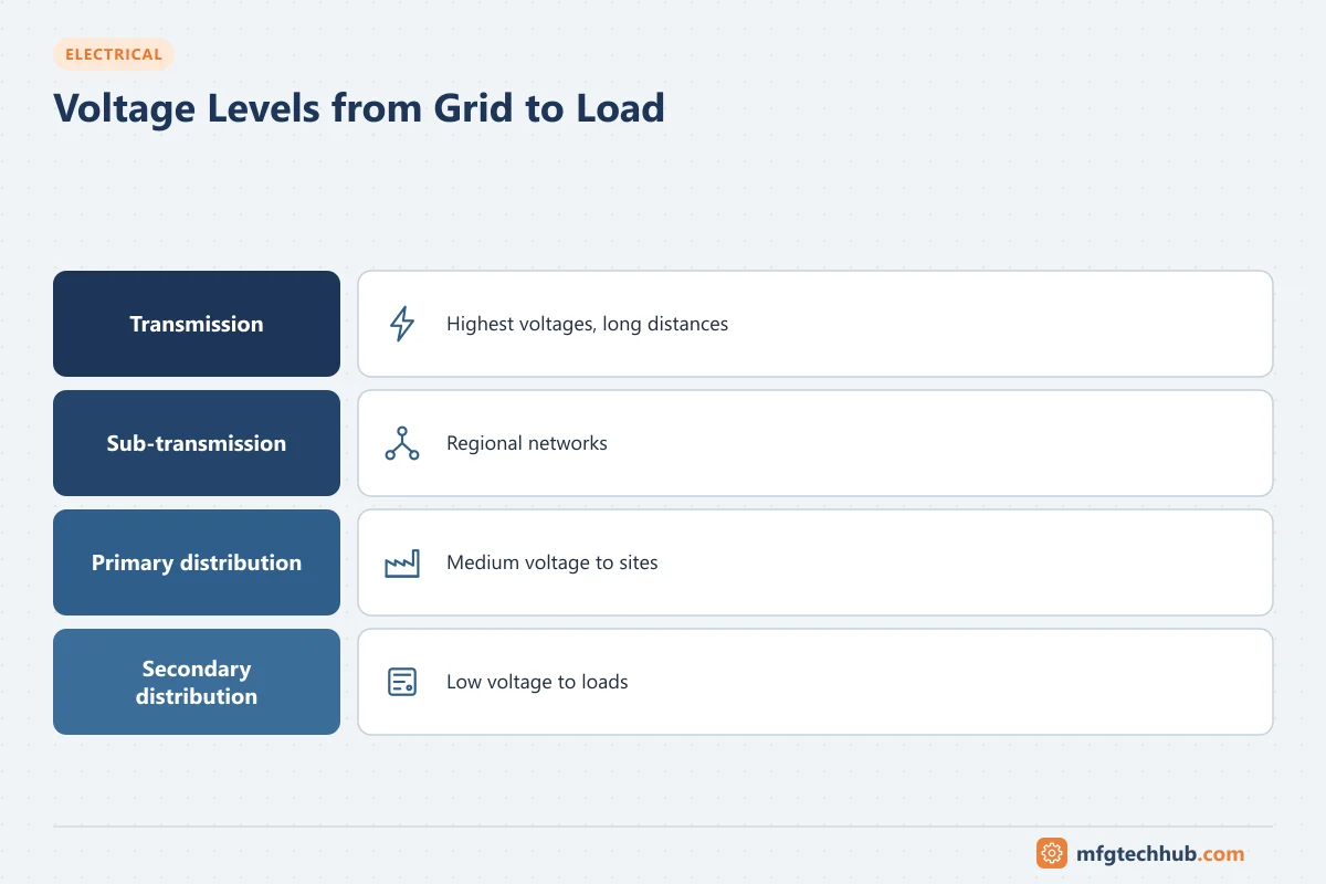
Doubling the voltage halves the current and reduces resistive losses to one quarter. That is why power is generated at medium voltage, stepped up for transmission, and stepped down in stages near the point of use.
| Level | Typical voltages (varies by country) | Purpose |
|---|---|---|
| Transmission | 220-765 kV | Bulk power over long distances |
| Sub-transmission | 66-138 kV | Regional supply, large industrial users |
| Primary distribution | 11-33 kV | Local networks, most industrial sites |
| Secondary distribution / utilization | 400/415/480 V, 230/120 V | Motors, lighting, equipment |
Large industrial plants may receive power directly at 66, 110 or 132 kV and have their own main substation.
How a transformer works
A transformer has primary and secondary windings on a laminated iron core. AC current in the primary creates an alternating magnetic flux that induces voltage in the secondary:
V₁ ÷ V₂ = N₁ ÷ N₂ I₁ ÷ I₂ ≈ N₂ ÷ N₁A step-down transformer has fewer secondary turns, so voltage decreases and current increases in the same proportion (ignoring losses).
Key transformer ratings
| Rating | Meaning |
|---|---|
| Rated power (kVA / MVA) | Continuous apparent power the transformer can supply |
| Voltage ratio | For example 11,000 / 433 V |
| Vector group | Winding connections and phase shift, for example Dyn11 (delta primary, star secondary with neutral, 30° phase shift) |
| Impedance (%Z) | Percentage of rated voltage needed to drive rated current through a short-circuited secondary; limits fault current and affects voltage regulation |
| Cooling type | For example ONAN (oil natural, air natural) or ONAF (oil natural, air forced) |
| Losses | No-load (core) losses and load (copper) losses |
| Insulation and temperature rise | Limits for oil and winding temperatures |
Why Dyn11 is common for distribution
A delta primary blocks triplen harmonics from reaching the upstream network, while the star secondary provides a neutral for single-phase loads and system earthing.
Fault level from transformer impedance
The transformer’s impedance largely determines the maximum short-circuit current on the LV side:
Full-load current I = S ÷ (√3 × V)
Approximate fault current Isc ≈ I × 100 ÷ %Z   (assuming an infinite upstream source)
Example: a 2,000 kVA, 11 kV / 433 V transformer with 6% impedance:
- I = 2,000,000 ÷ (√3 × 433) ≈ 2,667 A
- Isc ≈ 2,667 × 100 ÷ 6 ≈ 44.4 kA
Switchgear and breakers on the LV side must be rated for at least this fault current. See Industrial Circuit Breakers and Fuse Protection.
Voltage regulation and tap changers
Voltage at the secondary falls as load increases, because of transformer impedance, and it varies with the incoming supply. Tap changers adjust the turns ratio:
- Off-circuit (de-energized) tap changers: set during commissioning, typically ±2.5% and ±5% steps
- On-load tap changers (OLTC): adjust automatically under load using an automatic voltage regulator (AVR); common on larger transformers and substation units
Transformer types in industry
| Type | Characteristics | Typical use |
|---|---|---|
| Oil-immersed | High efficiency, good overload capacity, outdoor installation | Main substations, outdoor units |
| Cast resin (dry type) | No oil, reduced fire risk | Indoors, buildings, near loads |
| Isolation / control transformers | Small ratings; separate control circuits from power | Control panels |
| Drive (converter-duty) transformers | Designed for harmonics; multiple secondaries for 12- or 18-pulse drives | Large VFDs |
| K-rated transformers | Designed for harmonic loads | Data centers, electronic loads |
Efficiency and losses
Transformers are very efficient, often above 98-99%, but they are energized continuously, so no-load losses occur 24 hours a day. Energy-efficient transformers with lower-loss core materials can save considerable energy over a 25-40 year life. Many regions set minimum efficiency requirements for distribution transformers.
Safety considerations
- Transformers must be installed with suitable clearances, fire barriers and oil containment (for oil-filled units).
- Earthing of the neutral and frame must follow the system earthing design.
- Access to live parts must be restricted; switching follows safe operating procedures.
Key takeaways
- High voltage reduces current and losses, so power is transmitted at high voltage and stepped down near the load.
- Transformer ratio, vector group and impedance define its behavior; %Z sets the LV fault level.
- Tap changers maintain voltage; transformer type depends on location, fire risk and load.
Related tutorials
Before you apply this in a plant: this article is for education. Always check the current edition of the relevant standards, the manufacturer's documentation for your exact product and version, and your site's procedures. Safety-related work needs qualified personnel. See our editorial policy.