
LCR Meters and Electronic Component Testing
On this page
Every electronic assembly depends on components that meet their specifications. An LCR meter measures inductance (L), capacitance (C) and resistance (R), along with related parameters such as ESR, quality factor and dissipation factor. It is used in incoming inspection, production testing, repair and design validation of electronic and electrical equipment.
Why a multimeter is not enough
Many multimeters measure capacitance and resistance, but only with DC or a single simple method. Real components behave differently at different frequencies:
- A capacitor has equivalent series resistance (ESR) and inductance that affect its performance in power supplies.
- An inductor has winding resistance and capacitance between turns.
- Component values change with frequency, voltage and temperature.
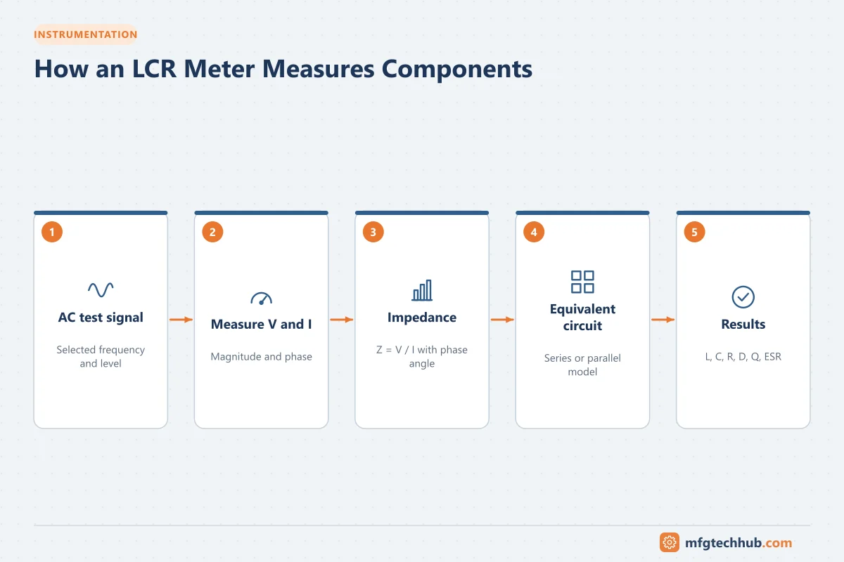
An LCR meter measures impedance with an AC test signal at a chosen frequency and level, giving a much more complete picture.
How an LCR meter works
The meter applies an AC voltage at a selected frequency, measures the resulting current and the phase angle between them, and calculates complex impedance:
Z = V ÷ I = R + jX
X_L = 2πfL        X_C = 1 ÷ (2πfC)
From impedance and phase, it calculates L, C, R and secondary parameters.
Test frequency and level
| Setting | Why it matters |
|---|---|
| Test frequency | Common choices are 100 Hz, 120 Hz, 1 kHz, 10 kHz and 100 kHz; measure at the frequency the component will operate at |
| Test voltage | Some components (ceramic capacitors, magnetic cores) change value with signal level |
| DC bias | Measuring inductors or capacitors under realistic operating current or voltage |
Example: electrolytic capacitors are commonly specified at 120 Hz (100 Hz in some regions), while ESR for switching power supplies is often specified at 100 kHz.
Series vs parallel equivalent circuits
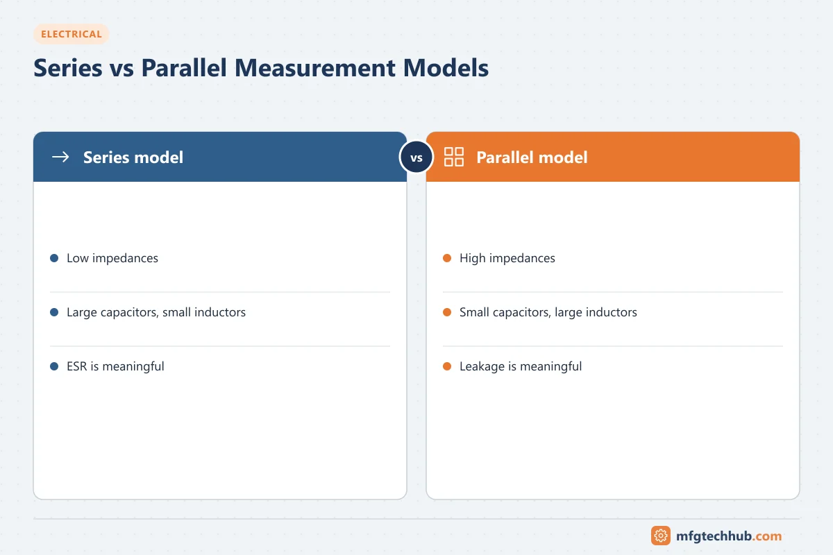
The meter models a component as either a series or parallel combination of an ideal element and a resistance:
- Series model: best for low impedances, such as large capacitors and small inductors
- Parallel model: best for high impedances, such as small capacitors and large inductors
Using the wrong model gives misleading values. Many meters select automatically.
Secondary parameters
| Parameter | Meaning | Use |
|---|---|---|
| ESR (equivalent series resistance) | Resistive losses in a capacitor | High ESR indicates ageing electrolytic capacitors, a common failure in power supplies and drives |
| D (dissipation factor) | Ratio of loss to reactance (tan δ) | Capacitor and insulation quality |
| Q (quality factor) | Ratio of reactance to resistance, Q = 1/D | Inductor and resonant circuit quality |
| θ (phase angle) | Phase between voltage and current | Distinguishes inductive and capacitive behavior |
| DCR | DC resistance of a winding | Inductor and transformer winding checks |
Types of LCR meters
- Handheld LCR meters: portable, limited frequency range, ideal for repair and field checks
- Benchtop LCR meters: wide frequency range, high accuracy, programmable, used in labs and production
- Impedance analyzers: sweep impedance across a wide frequency range for detailed characterization
- Component testers and ESR meters: simple dedicated tools for repair work
Accurate measurement techniques
- Use the right fixture: Kelvin (four-terminal) clips or test fixtures reduce the effect of lead resistance, especially for low impedances.
- Perform open and short compensation with the fixture before measuring, to cancel stray capacitance and lead impedance.
- Discharge capacitors before connecting them to the meter.
- Measure out of circuit when possible; parallel components in a circuit distort readings.
- Control temperature for precise work, because component values drift with temperature.
Applications in manufacturing and maintenance
Incoming inspection and production
Sample or test components to confirm they meet specifications, detect counterfeit or mislabeled parts, and verify transformers and inductors in finished assemblies.
Repair of industrial electronics
- Checking electrolytic capacitors in VFDs, UPS systems and power supplies; rising ESR and falling capacitance indicate end of life
- Testing inductors and chokes for shorted turns (low Q or inductance)
- Checking relay and solenoid coils and current transformers
Sensor and cable testing
LCR meters can measure capacitance of cables and capacitive sensors, and inductance of inductive proximity sensor coils and LVDTs during troubleshooting.
Key takeaways
- LCR meters measure impedance at a chosen AC frequency, giving L, C, R and loss parameters.
- Test frequency, level and the series/parallel model must match the component and application.
- ESR, D and Q reveal component quality and ageing that simple meters miss.
- Proper fixtures and open/short compensation are essential for accurate results.
Related tutorials
Before you apply this in a plant: this article is for education. Always check the current edition of the relevant standards, the manufacturer's documentation for your exact product and version, and your site's procedures. Safety-related work needs qualified personnel. See our editorial policy.