
Power Factor Correction: Calculation, Capacitor Banks and Efficiency
On this page
A plant can pay for electricity it never uses productively. When power factor is low, cables, transformers and switchgear carry more current than the useful work requires, losses increase, and many utilities charge penalties. Power factor correction (PFC) reduces this wasted current, often with a short payback period.
What is power factor?
In an AC system, inductive loads such as induction motors and transformers need reactive power (kvar) to create magnetic fields. Reactive power does no useful work but still flows through the network.
| Quantity | Unit | Meaning |
|---|---|---|
| Active power (P) | kW | Real power that does work |
| Reactive power (Q) | kvar | Power that maintains magnetic fields |
| Apparent power (S) | kVA | Total power the system must carry |
These form the power triangle:
S² = P² + Q² Power factor (PF) = P ÷ S = cos φA PF of 1.0 means all current does useful work. A PF of 0.75 means that for every 75 kW of useful power, the system carries 100 kVA.

Why low power factor is a problem
- Higher current for the same useful power, increasing I²R losses in cables and transformers
- Reduced capacity: transformers and cables may reach their limits sooner
- Larger voltage drops
- Utility penalties or kVA-based demand charges
Common causes of low power factor
- Lightly loaded induction motors (a motor at 25% load has a much lower PF than at full load)
- Transformers operating at light load
- Welding equipment and induction furnaces
- Fluorescent lighting with magnetic ballasts
Note: VFDs with diode rectifiers usually have a good displacement power factor, but they draw harmonic currents, which lower the true (total) power factor. Capacitors do not fix harmonic distortion.
Calculating the correction required
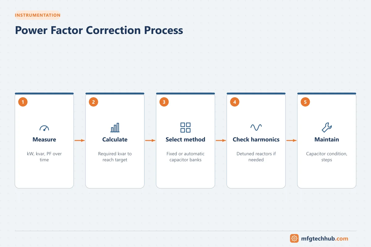
To raise power factor from PF₁ to PF₂ for a load of P kW:
Qc (kvar) = P × (tan φ₁ − tan φ₂) where φ = arccos(PF)Worked example: a plant load of 500 kW at PF 0.75 is to be corrected to 0.95.
- tan(arccos 0.75) = 0.882
- tan(arccos 0.95) = 0.329
- Qc = 500 × (0.882 − 0.329) ≈ 277 kvar
Apparent power falls from 500 ÷ 0.75 ≈ 667 kVA to 500 ÷ 0.95 ≈ 526 kVA, reducing current by about 21%.
Methods of correction
Individual (fixed) correction at motors
A capacitor is connected directly at a motor terminal and switches with the motor. It is simple and reduces current in the feeder cable, but capacitor sizing must avoid self-excitation when the motor is switched off. Never connect capacitors to the output of a VFD.
Group correction
Capacitors serve a group of loads at a distribution board.
Central automatic correction
An automatic power factor correction (APFC) panel at the main switchboard contains several capacitor steps. A PF controller measures the network and switches steps in and out to maintain a target PF as the load changes. This is the most common industrial approach.
Detuned capacitor banks (with harmonics)
Capacitors and network inductance form a resonant circuit. If the resonance frequency coincides with a harmonic produced by drives or rectifiers, currents and voltages can amplify dangerously, causing capacitor failures and nuisance trips. Detuned banks add a series reactor to each step, tuning the resonance below the lowest significant harmonic (for example, a 7% reactor tunes to about 189 Hz on a 50 Hz network, below the 5th harmonic at 250 Hz). Detuned banks are strongly recommended in plants with many VFDs.
Active and synchronous correction
- Active power factor correction / static var generators use power electronics to supply reactive power quickly and smoothly, and some also filter harmonics.
- Synchronous motors and condensers can be over-excited to supply reactive power.
Maintenance of capacitor banks
- Inspect for bulging or leaking capacitors, and check temperatures with infrared thermography
- Measure capacitance and step currents periodically; capacitors lose capacitance with age
- Check contactors (special capacitor-duty contactors limit inrush)
- Ensure ventilation, since heat shortens capacitor life
- Verify that discharge resistors work before touching terminals
Target power factor
Many sites aim for 0.95 to 0.98. Overcorrecting to a leading power factor at light load can cause voltage rise and is often also penalized. Check your utility tariff for the required value and the measurement method.
Key takeaways
- Power factor is the ratio of useful power (kW) to total apparent power (kVA).
- Low power factor increases current, losses and utility charges.
- Required correction is Qc = P × (tan φ₁ − tan φ₂).
- In plants with drives and harmonics, use detuned or active correction to avoid resonance.
Related tutorials
Before you apply this in a plant: this article is for education. Always check the current edition of the relevant standards, the manufacturer's documentation for your exact product and version, and your site's procedures. Safety-related work needs qualified personnel. See our editorial policy.