
Loop Calibrators for Process Control: How to Test 4-20 mA Loops
On this page
A loop calibrator is one of the most-used tools in an instrument technician’s kit. It can measure a 4-20 mA signal, source a current to test a control system input or valve positioner, simulate a transmitter, and power a loop. Multifunction and documenting calibrators extend this to temperature, pressure and HART communication, making calibration faster and better documented.
Loop calibrator functions
| Mode | What it does | Typical use |
|---|---|---|
| Measure (read) mA | Measures loop current in series with the loop | Checking a transmitter’s output |
| Measure with loop power | Supplies 24 V DC and measures current | Testing a transmitter on the bench or disconnected from the system |
| Source mA | Generates a current into a passive input | Testing a PLC/DCS input, a valve positioner or an indicator |
| Simulate (sink) mA | Regulates current in a loop powered by the system, acting like a 2-wire transmitter | Checking the control system input and alarms without the transmitter |
| Measure / source voltage | Tests 1-5 V or 0-10 V signals | Voltage inputs and outputs |
| Ramp and step | Automatically ramps or steps the output | Testing alarms, trips and valve travel |
Tip: many calibrators have a 250 Ω HART resistor that can be switched in when powering a loop, so that a HART communicator can talk to the transmitter.
Multifunction and documenting calibrators
- Multifunction process calibrators also source and measure thermocouple, RTD, frequency and pressure signals (with pressure modules).
- Documenting calibrators store calibration procedures and results, and upload them to calibration management software, removing handwritten records.
- HART-capable calibrators can read and adjust smart transmitter settings (range, trim) during calibration.
Accuracy and traceability
The calibrator must be significantly more accurate than the instrument under test. A common guideline is a test uncertainty ratio (TUR) of at least 4:1. Calibrators themselves must be calibrated periodically by a laboratory with traceability to national standards, often accredited to ISO/IEC 17025.
See Instrument Calibration and Standardization.
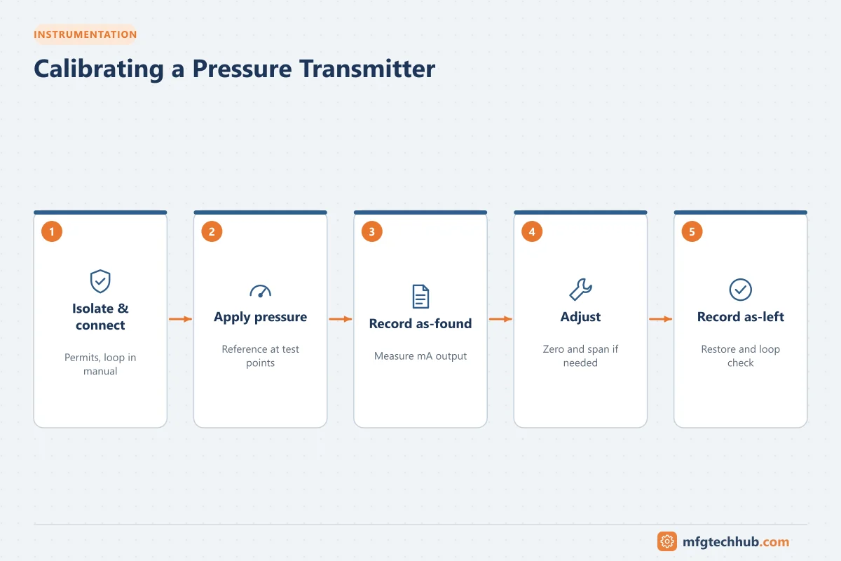
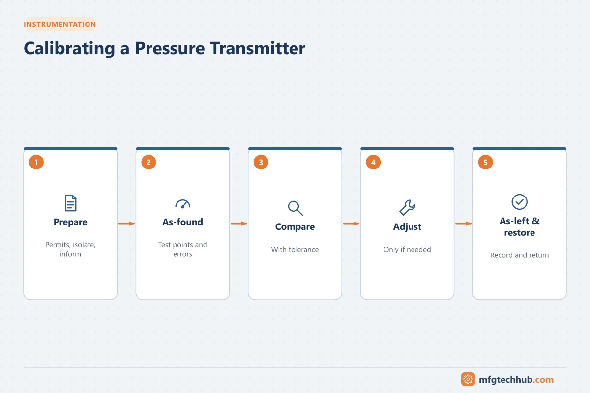
Calibrating a pressure transmitter: step by step
Equipment: loop calibrator (with 24 V loop power), pressure source (hand pump or pressure calibrator) and reference pressure gauge or module.
- Prepare: obtain the work permit, inform operations, put the loop in manual or bypass trips as authorized, and isolate the transmitter from the process.
- Connect: apply pressure from the calibrator to the transmitter; connect the loop calibrator in measure-with-loop-power mode (or in series with the live loop).
- As-found test: apply pressures at 0%, 25%, 50%, 75% and 100% of range and record the output current at each point. Optionally repeat descending to check hysteresis.
- Calculate errors:
Expected mA = 4 + 16 × (applied − LRV) ÷ (URV − LRV)
Error (% of span) = (measured mA − expected mA) ÷ 16 × 100- Compare with tolerance: if errors are within tolerance (for example ±0.25% of span), no adjustment is needed.
- Adjust if needed: perform sensor trim and output (analog) trim, using HART or local adjustments.
- As-left test: repeat the test points and record results.
- Restore: reconnect to process, remove bypasses, return the loop to service and inform operations.
- Document: record as-found and as-left data, equipment used and its calibration status.
Example: a 0-10 bar transmitter at 5 bar should output 12.000 mA. If it reads 12.040 mA, the error is 0.040 ÷ 16 × 100 = 0.25% of span.
Use our 4-20 mA calculator to check expected values.
Testing a control system input
With the transmitter disconnected, use simulate mode at the field terminals (or source mode for passive inputs):
- Inject 4, 8, 12, 16 and 20 mA.
- Confirm the displayed value in the DCS/PLC matches the expected engineering value.
- Check alarm points by ramping slowly through them.
- Check open-loop behavior: what does the system show at 3.6 mA or below (NAMUR NE 43 failure)?
Testing a control valve
Use source mode to drive the positioner:
- Send 4, 8, 12, 16 and 20 mA and check valve travel at 0, 25, 50, 75 and 100%.
- Check stroke in both directions for hysteresis.
- Verify fail-safe action on loss of signal or air.
Loop checks during commissioning
A loop check verifies the complete path from field device to operator display and back, confirming correct wiring, tags, ranges, alarms and control action. The loop calibrator is the core tool, used together with instrument loop diagrams (ISA-5.4). See P&ID Standards.
Safety considerations
- Follow permit-to-work and hazardous area procedures; use intrinsically safe calibrators in hazardous areas.
- Never disconnect a loop without confirming the effect on control and safety systems.
- Be careful with trips and interlocks during testing; use authorized bypasses.
Key takeaways
- Loop calibrators measure, source, simulate and power 4-20 mA loops.
- Calibrate with multiple test points, recording as-found and as-left data.
- Calculate error as a percentage of span and compare with tolerance.
- Documenting and HART-capable calibrators speed up work and improve records.
Related tutorials
Before you apply this in a plant: this article is for education. Always check the current edition of the relevant standards, the manufacturer's documentation for your exact product and version, and your site's procedures. Safety-related work needs qualified personnel. See our editorial policy.