
DCS Hierarchy and Layers: Levels 0 to 4, Where Each Function Belongs and How Data Flows
On this page
A distributed control system is organised in levels, from the instruments on the process up to the business systems. The levels are not just a drawing convention: they decide where each function runs, how fast it must respond, what happens when a level fails, and how the system is protected. Most architecture mistakes come from putting a function at the wrong level, for example control logic in a server or business users on the control network.
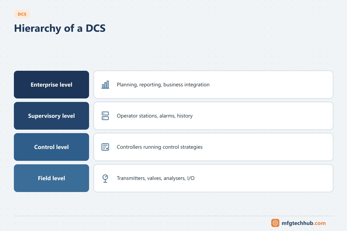
The level numbers used here follow the functional hierarchy of ISA-95 (IEC 62264), which is closely related to the Purdue reference model used in security design.
The levels at a glance
| Level | Name | What sits here | Typical time scale |
|---|---|---|---|
| 0 | Physical process | Process equipment, sensors, actuators | Continuous |
| 1 | Sensing and control | I/O modules, DCS controllers, safety logic solvers | Milliseconds to seconds |
| 2 | Supervisory control | Operator and engineering stations, DCS servers, DCS historian, APC | Seconds to minutes |
| 3 | Operations management | Plant historian, MES, LIMS, batch records, asset management | Minutes to days (shifts, batches) |
| 4 | Business planning | ERP, scheduling, supply chain | Days to months |
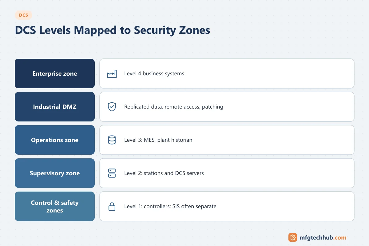
Between levels 3 and 4 there is usually an industrial DMZ that holds replicated data and remote-access and patch servers, so no direct connection is needed between the business network and the control system.
Where each function belongs
| Function | Correct level | Why |
|---|---|---|
| PID control, interlocks, motor and valve logic | 1 (controllers) | Must keep running if stations, servers or networks above fail |
| Safety instrumented functions | 1 (separate SIS) | Independence from the control system (IEC 61511) |
| Sequences and batch phases | 1 (phase logic), 2 (batch management) | Phases must complete safely; recipe management needs the server |
| Alarm detection | 1 | Close to the source and timestamped there |
| Alarm presentation, acknowledgement | 2 | Operator interface |
| Advanced process control (MPC) | 2 | Writes setpoints to level 1 loops; plant stays safe if APC stops |
| Short-term history and trends | 2 | Operator and engineer troubleshooting |
| Long-term history for the site | 3 | Business users, analysis, reports |
| Production orders, genealogy, quality records | 3 | MES functions |
| Planning and costing | 4 | ERP |
The test for any function: what happens to the process if this level stops? If the answer is “the plant becomes unsafe or trips”, the function is at too high a level.
How data and commands flow
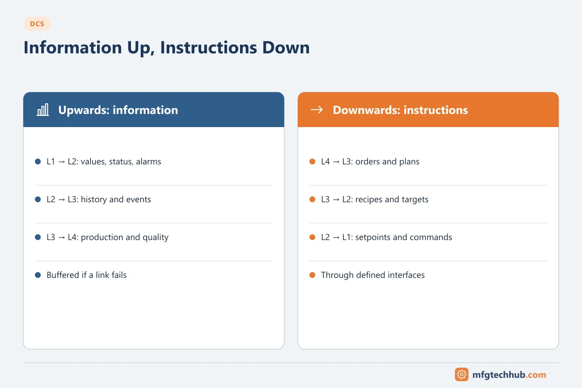
Upwards (information):
- Level 1 publishes values, status and alarms to level 2.
- Level 2 stores history and events, and replicates them to level 3 (plant historian, MES).
- Level 3 summarises production, consumption and quality for level 4 (ERP).
Downwards (instructions):
- Level 4 sends production orders and plans to level 3.
- Level 3 sends orders, recipes or targets to level 2, often through a batch system or operator.
- Level 2 sends setpoints, modes and commands to level 1.
- Level 1 drives the process at level 0.
Each boundary is a defined interface with a known owner. A direct write from MES or a business application into a controller bypasses the operator and the checks at level 2 and should be avoided or tightly controlled. See How MES Integrates with ERP, SCADA and PLC.
What happens when a level fails
| Failure | Effect on the process | Design response |
|---|---|---|
| Level 4 or 3 system down | None immediately; orders and records delayed | Local buffering; manual procedures |
| DMZ or firewall down | None; business users lose data | Historians buffer and backfill |
| Level 2 servers or stations down | Control continues; operators may lose view | Redundant servers and several stations per area |
| One controller down | Its area loses control unless redundant | Redundant controllers; outputs to fail-safe state |
| SIS demand | Process taken to a safe state | Independent of all DCS levels |
Safety system placement
The safety instrumented system (SIS) sits alongside the DCS at level 1 with its own logic solvers, I/O and usually its own sensors and final elements. It is integrated for operation (operators see SIS status and alarms on DCS stations) but separated for protection (the SIS does not depend on DCS controllers, networks or servers to act). See Functional Safety.
Security zones
The levels map naturally onto zones and conduits in an ISA/IEC 62443 design:
- Level 0–1 control and safety equipment in one or more control zones (safety often in its own zone).
- Level 2 supervisory systems in a supervisory zone.
- Level 3 plant systems in an operations zone.
- An industrial DMZ between level 3 and the enterprise.
- Traffic between zones only through defined conduits (firewalls, data diodes where justified) with defined, documented connections.
For networks and redundancy protocols at each level, see DCS Network Topologies and Protocols and OT Network Design Fundamentals.
Common allocation mistakes
| Mistake | Consequence | Better approach |
|---|---|---|
| Control logic in a server script or historian calculation | Loop stops when the server restarts | Implement in the controller |
| Safety trips implemented in the DCS | No independence; SIL claims invalid | Separate SIS per IEC 61511 |
| Business users connecting to DCS servers | Load and security risk on level 2 | Replicate to a level 3 historian or DMZ |
| MES writing directly to controller tags | Bypasses operator and checks | Orders through batch system or operator with defined interface |
| Remote vendor access straight to engineering stations | Uncontrolled path into level 2 | Remote access through the DMZ with approval and logging |
Frequently asked questions
What are the levels of a DCS?
Level 0 is the process and field devices, level 1 the I/O and controllers, level 2 the operator stations and DCS servers, level 3 plant operations systems such as MES and the plant historian, and level 4 business systems such as ERP. The DCS proper covers levels 1 and 2.
Is the Purdue model the same as ISA-95?
They are closely related. ISA-95 defines the functional hierarchy (levels 0 to 4) for integrating control and business systems. The Purdue reference model, from which it derives, is widely used in OT security to define network zones, often with an added DMZ level.
Where does the SIS sit in the DCS hierarchy?
At level 1 alongside the DCS controllers, but as an independent system with its own logic solvers and I/O, integrated with the DCS only for operator information.
Key takeaways
- The DCS covers levels 1 and 2; levels 3 and 4 hold operations and business systems.
- Put each function at the lowest level that can perform it reliably; control must not depend on higher levels.
- Data flows up as information, instructions flow down through defined interfaces.
- The SIS is independent, and the levels map onto IEC 62443 security zones.
Related tutorials
Before you apply this in a plant: this article is for education. Always check the current edition of the relevant standards, the manufacturer's documentation for your exact product and version, and your site's procedures. Safety-related work needs qualified personnel. See our editorial policy.