
DCS Field Devices: Connecting Transmitters, Valves and Motors to the Control System
On this page
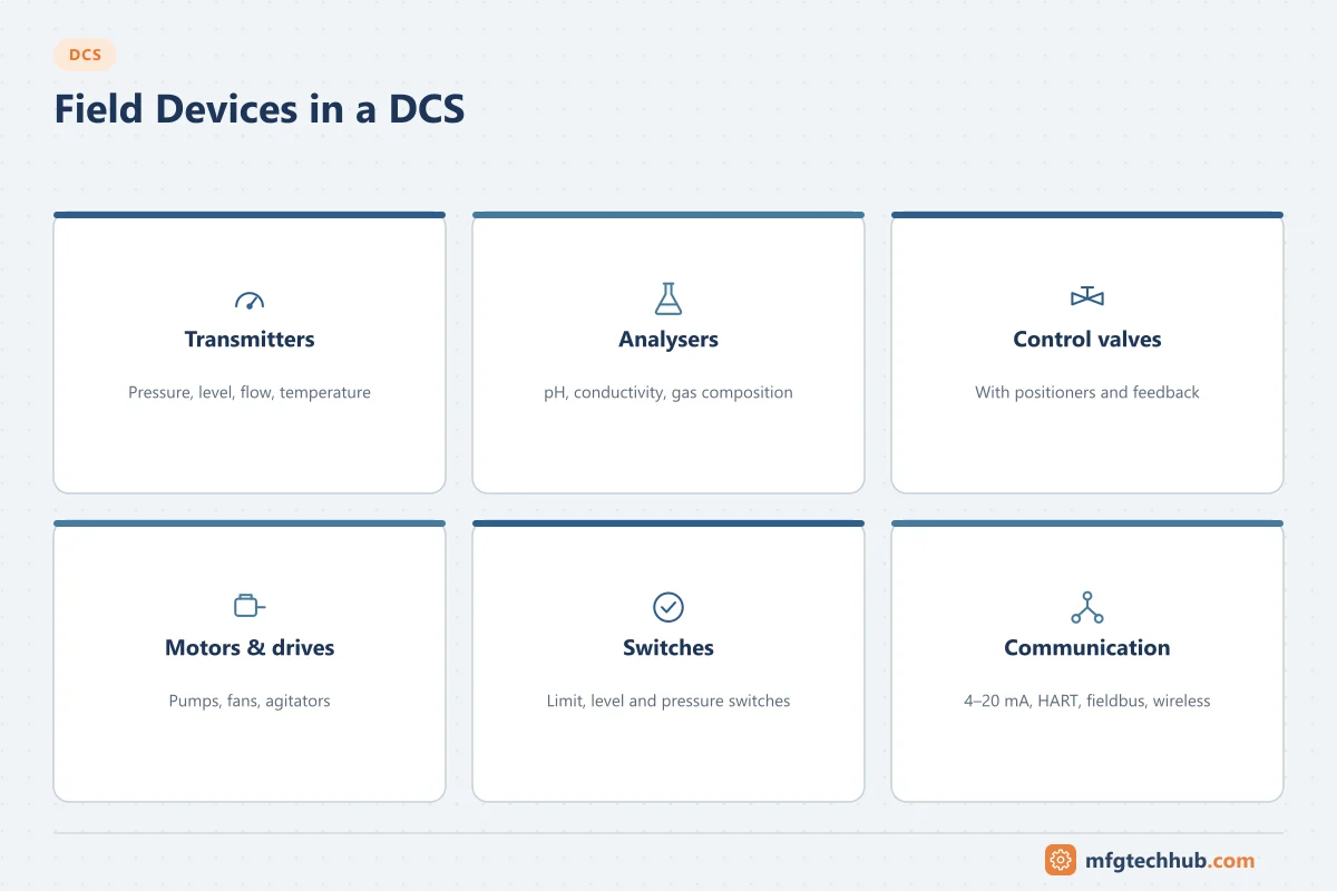
Field devices are the instruments and actuators installed on the process: transmitters, analysers, switches, control valves, motors and drives. The DCS knows the process only through them and can act on it only through them. Most control problems that operators blame on the DCS turn out to be field device problems: a plugged impulse line, a sticking valve, a transmitter with the wrong range.
This page explains how field devices connect to and integrate with the DCS. For how the instruments themselves work, see the Instrumentation series.
Device types and typical DCS signals
| Device | Examples | Typical DCS connection |
|---|---|---|
| Transmitters | Pressure, differential pressure, level, flow, temperature | 4–20 mA with HART, fieldbus, wireless |
| Analysers | pH, conductivity, oxygen, gas chromatographs | 4–20 mA, Modbus or OPC UA from analyser systems |
| Switches | Level, pressure, limit switches | Discrete input |
| Control valves | Globe, butterfly, ball valves with positioners | 4–20 mA with HART to the positioner, or fieldbus |
| On/off valves | Shutdown and isolation valves with solenoids | Discrete output plus limit switch feedback |
| Motors and drives | Pumps, fans, agitators, variable speed drives | Discrete I/O for start/stop/run; drive networks for speed and diagnostics |
See Pressure Transmitters, Flowmeter Selection, Level Measurement Selection and Actuators and Control Valves.
Ways to connect field devices
| Technology | How it works | Strengths | Points to watch |
|---|---|---|---|
| 4–20 mA + HART | Analog signal for control; HART digital data on the same pair | Simple, universal, robust; diagnostics via HART | One pair per device; HART data is slow |
| FOUNDATION Fieldbus H1 | Digital bus, several devices per segment; function blocks can run in devices | Fewer cables, rich diagnostics | Segment design, power conditioning, specialist skills |
| PROFIBUS PA | Digital bus coupled to PROFIBUS DP | Common in Siemens-based plants | Segment design and couplers |
| WirelessHART / ISA100 Wireless | Battery-powered wireless instruments in a mesh | No cables; fast for monitoring points | Update rates and battery life; mainly monitoring, not fast control |
| Ethernet-APL | Two-wire Ethernet to the field, including hazardous areas | High bandwidth, one network from field to control | New technology; device availability growing |
| Discrete I/O | 24 V DC contacts and outputs | Simplest | No diagnostics beyond line monitoring |
Most plants use a mix: 4–20 mA with HART for the majority, fieldbus or APL where the project chose it, wireless for monitoring points that would be expensive to cable. See HART Protocol Explained and Industrial Communication Protocols.
Device integration and asset management
Digital devices describe themselves to the DCS and asset management software through device description technologies:
| Technology | Role |
|---|---|
| EDDL (Electronic Device Description Language) | Text-based description of device parameters and menus |
| FDT/DTM | Device-specific software component (DTM) running in an FDT frame application |
| FDI (Field Device Integration) | Combines EDD and user-interface elements in one package |
With these, an asset management system connected through the DCS I/O can read diagnostics, compare configurations, record calibrations and change device settings without going to the field. Keep device description files up to date as devices and firmware change.
Diagnostics: NAMUR NE 107
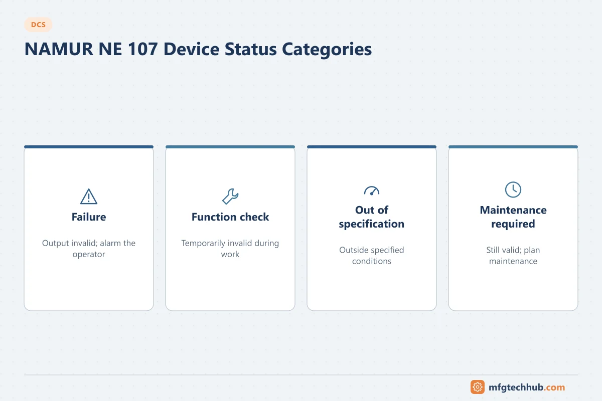
Smart devices generate many diagnostic messages. NAMUR NE 107 groups them into four status categories so maintenance and operators see a consistent picture:
| NE 107 status | Meaning | Typical response |
|---|---|---|
| Failure | Output signal invalid | Operator alarm; maintenance urgent |
| Function check | Output temporarily invalid due to work on the device | Expected during maintenance; operator informed |
| Out of specification | Device operating outside its specified range or conditions | Check process conditions or device |
| Maintenance required | Still valid, but maintenance needed soon | Plan maintenance |
Route failures to operators and maintenance statuses to the maintenance team, not to the operator alarm list. For analog signals, the transmitter’s failure current (per NAMUR NE 43) tells the DCS input that the value is invalid. See SCADA Data Acquisition for how failure signals are handled.
Hazardous areas
Devices in potentially explosive atmospheres need a protection concept, commonly intrinsic safety (Ex i) for instrumentation signals, with isolators or barriers between the field and the DCS I/O, or flameproof enclosures (Ex d). The protection concept affects the I/O choice, cable design and maintenance practice: intrinsically safe loops require certified devices, documented loop parameters and care when replacing parts. See Safety in Industrial Electrical and Instrumentation.
Commissioning: loop checks
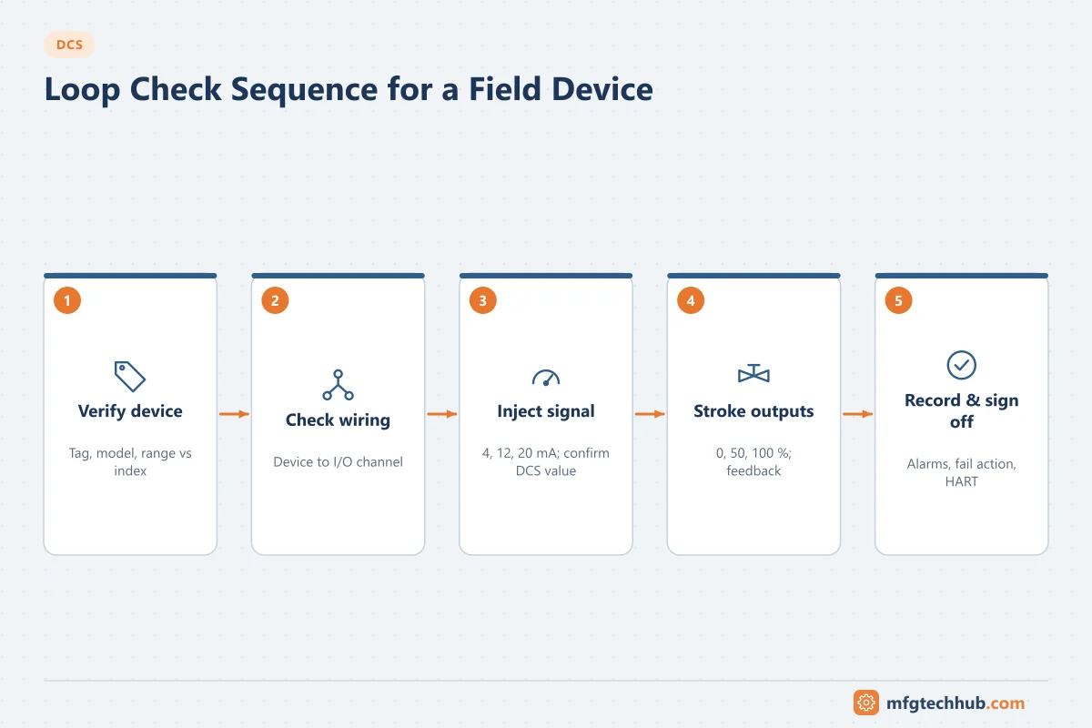
Before start-up, every field device is checked end to end:
- Confirm the device tag, model and range against the instrument index.
- Check the wiring from device to junction box, marshalling and I/O channel.
- Inject or simulate the signal at the device (for example 4, 12 and 20 mA) and confirm the DCS value and range.
- For outputs, command 0, 50 and 100 % and confirm the valve position or motor action and feedback.
- Check alarms, fail-safe action and HART or fieldbus communication.
- Record the result and sign off the loop.
See DCS System Integration and Calibration and Loop Calibrators.
Common field device faults seen in the DCS
| What the DCS shows | Possible field cause | First check |
|---|---|---|
| Value stuck, good quality | Plugged impulse line, frozen sensor, stuck float | Compare with local gauge; blow down impulse lines |
| Noisy value | Process turbulence, electrical noise, poor grounding | Transmitter damping; shield and grounding |
| Value offset from reality | Wrong range, zero drift, wrong density or configuration | Transmitter range vs DCS range; calibration |
| Bad quality / failure alarm | Open circuit, device failure, NE 43 failure current | Loop current; device diagnostics |
| Valve does not follow output | Low air supply, positioner fault, stiction | Positioner diagnostics; valve signature test |
| Motor running feedback missing | Auxiliary contact or wiring fault | Contact status at the MCC |
See Instrument Troubleshooting and Common Instrument Failures.
Frequently asked questions
What are field devices in a DCS?
The instruments and actuators on the process: transmitters, analysers, switches, control valves, motors and drives. They connect to DCS I/O through analog, discrete, fieldbus, wireless or Ethernet-APL signals.
Is 4–20 mA still used with modern DCS?
Yes. 4–20 mA with HART remains the most common connection for transmitters and valve positioners because it is simple and robust. HART adds digital diagnostics and configuration over the same wires.
What is NAMUR NE 107?
A NAMUR recommendation that groups field device diagnostics into four categories: failure, function check, out of specification and maintenance required, so that alarms and maintenance messages are consistent across devices.
Key takeaways
- The DCS is only as good as its field devices; many “DCS problems” are field problems.
- Choose connection technologies per device: 4–20 mA with HART, fieldbus, wireless or Ethernet-APL.
- Use device integration and NE 107 diagnostics to route the right information to operators and maintenance.
- Perform and record full loop checks before start-up.
Related tutorials
Before you apply this in a plant: this article is for education. Always check the current edition of the relevant standards, the manufacturer's documentation for your exact product and version, and your site's procedures. Safety-related work needs qualified personnel. See our editorial policy.