
Traditional vs Modern DCS Architecture: Layers, Components, Networks and Evolution
On this page
A distributed control system (DCS) spreads control functions across multiple controllers located near the process, while providing a single engineering database and operator environment for the whole plant. The concept has stayed the same since the first systems appeared in the mid-1970s, but the technology underneath has changed several times. Understanding both traditional and modern architectures matters because most plants run a mix of both, and migration projects must bridge them.
The layers of a DCS
Both traditional and modern systems follow a layered structure that aligns with the lower levels of the ISA-95 model:
| Layer | Function | Typical components |
|---|---|---|
| Field (Level 0–1) | Measure and act on the process | Transmitters, analysers, control valves, motors. See DCS Field Devices |
| I/O | Convert field signals to digital data | Analog/digital I/O cards, fieldbus interfaces, marshalling |
| Control (Level 1–2) | Execute control strategies | Redundant controllers running PID, logic and sequences. See Controllers and I/O Modules |
| Supervisory (Level 2) | Operate, alarm, trend, engineer | Operator stations, engineering stations, servers, historian. See DCS HMI |
| Integration (Level 3) | Share data with plant systems | Historian, MES, asset management, advanced process control |
A separate safety instrumented system (SIS) usually runs alongside the DCS, integrated for operation but independent for protection, as required by IEC 61511.
Traditional DCS architecture (roughly 1975–2000s)
Characteristics:
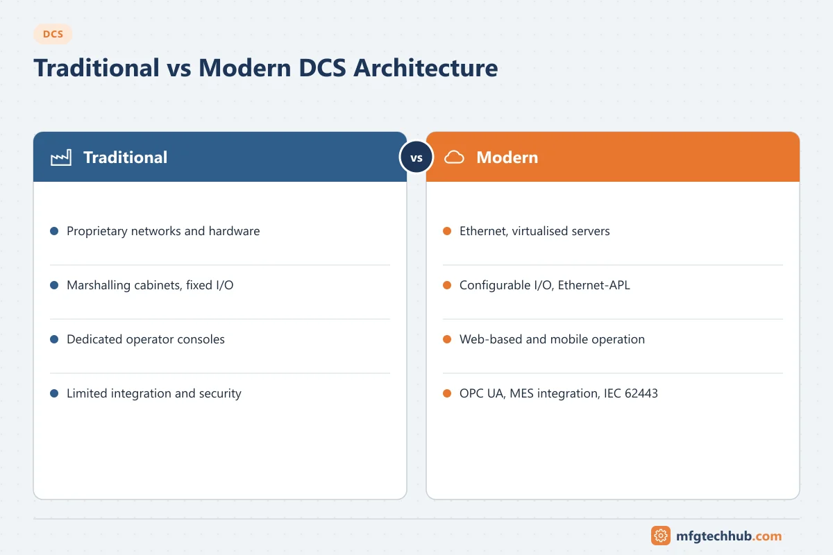
- Proprietary everything: controllers, I/O, networks, operator consoles and often the operating system were designed by the DCS vendor.
- Proprietary control networks (token-passing or vendor-specific highways), frequently redundant.
- Hard-wired 4–20 mA I/O with large marshalling cabinets: every field cable is cross-wired to a specific I/O channel.
- Dedicated operator consoles with vendor hardware and keyboards.
- Centralised engineering database within the vendor’s environment.
- Limited integration: data to business systems through gateways, often one-way and slow.
Strengths: very high reliability, deterministic behaviour, tightly integrated engineering and a single vendor responsible for the whole system.
Weaknesses: high cost, vendor lock-in, difficult integration with other systems, and hardware that becomes obsolete with few upgrade paths.
Transitional architecture (late 1990s–2010s)
- Operator and engineering stations moved to standard PCs and Windows.
- Control networks moved to redundant Ethernet (often with vendor-specific protocols and switches).
- OPC (Classic) became the common interface to historians and other systems.
- Fieldbus (FOUNDATION Fieldbus, PROFIBUS PA) and HART added digital device data and asset management.
This generation made DCS more open but introduced IT lifecycle issues: Windows patching, antivirus, domain management and cybersecurity.
Modern DCS architecture (2010s onwards)
| Area | Modern approach |
|---|---|
| Servers | Virtualised servers and thin-client operator stations; hardware can be replaced independently of the DCS software |
| I/O | Configurable or “electronically marshalled” I/O: channels are assigned by software, reducing marshalling cabinets and late design changes |
| Field networks | HART, FOUNDATION Fieldbus and PROFIBUS PA remain common; Ethernet-APL enables Ethernet directly to field instruments |
| Control network | Redundant industrial Ethernet with ring or parallel redundancy |
| Integration | OPC UA, historian interfaces, MES and asset management integration |
| Engineering | Class-based libraries, bulk engineering from instrument databases, simulation and virtual commissioning |
| Security | IEC 62443-aligned architectures, security zones, hardened configurations, patch and backup management |
| Modular plants | Module Type Package (MTP) to integrate process skids into the orchestration layer |
| Open architectures | Initiatives such as O-PAS (Open Process Automation Standard) aim for interoperable, multi-vendor control systems |
See Modern DCS network topologies and protocols for network details.
Side-by-side comparison
| Aspect | Traditional DCS | Modern DCS |
|---|---|---|
| Hardware | Proprietary consoles and computers | Standard servers, often virtualised; thin clients |
| Control network | Proprietary highway | Redundant industrial Ethernet |
| I/O and marshalling | Hard-wired, fixed channel assignment, large marshalling | Configurable I/O, reduced marshalling, remote I/O near the field |
| Field data | 4–20 mA only | 4–20 mA plus HART, fieldbus, Ethernet-APL, device diagnostics |
| Integration | Gateways, limited | OPC UA, historians, MES, asset management |
| Engineering | Manual, per loop | Templates, bulk engineering, simulation |
| Lifecycle | Hardware and software tightly coupled | Hardware and software lifecycles more independent; frequent patching needed |
| Cybersecurity | Isolation-based | Designed-in security controls plus network segmentation |
| Skills | Vendor-specific control engineering | Control engineering plus IT, networking and security |
Redundancy in both generations
Redundancy is a defining DCS feature:
- Controller redundancy: a primary and a hot-standby controller with synchronised data and bumpless switchover.
- Network redundancy: dual networks or ring/parallel redundancy protocols.
- Power supply redundancy for controllers and I/O.
- I/O redundancy for critical loops (redundant I/O cards, sometimes redundant transmitters).
- Server redundancy for operator displays, alarms and history.
What changed is how redundancy is implemented (for example virtual machine high availability for servers), not its importance.
Migrating from traditional to modern
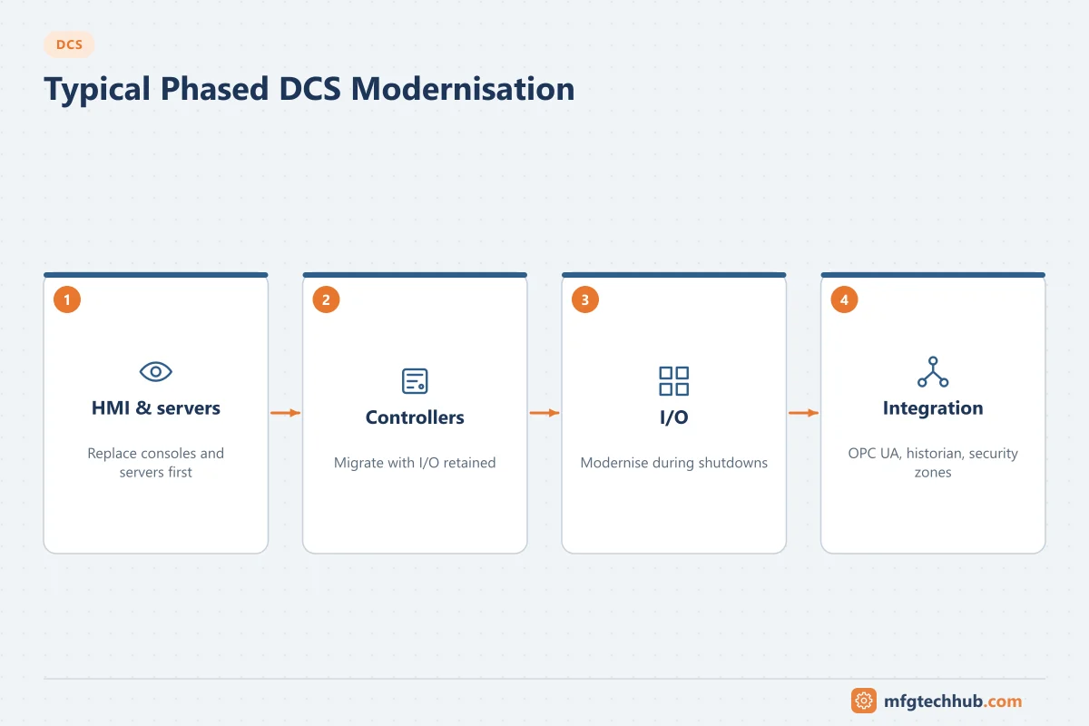
Most plants modernise in phases rather than replacing everything at once:
- HMI and servers first: replace consoles and servers while keeping controllers and I/O, using vendor migration paths.
- Controller migration with I/O retained through adapters or wiring conversion.
- I/O modernisation during major shutdowns.
- Integration upgrades: OPC UA, historian and MES connectivity, security zones.
Key considerations: keeping control strategies equivalent (or deliberately improved and tested), operator retraining, cutover planning around shutdowns, and management of change. The PLC Migration Guide covers many of the same principles.
Frequently asked questions
What is the main difference between a traditional and a modern DCS?
Traditional DCS used proprietary hardware, networks and consoles with hard-wired I/O. Modern DCS uses standard servers (often virtualised), industrial Ethernet, configurable I/O, digital field communication and open integration standards, with cybersecurity designed in.
Is a modern DCS less reliable because it uses standard IT technology?
Not inherently. Controllers remain purpose-built and redundant. The IT-based layers need good lifecycle management (patching, backups, security) to maintain reliability.
What is electronic marshalling?
It is an approach where field cables connect to configurable I/O channels that can be assigned to any controller in software, instead of cross-wiring each cable to a specific I/O card in a marshalling cabinet. It reduces cabinet space and makes late changes easier.
Key takeaways
- The DCS concept (distributed control with a common database and operator environment) has not changed.
- Traditional systems were proprietary and hard-wired; modern systems use Ethernet, virtualisation, configurable I/O and open integration.
- Most plants modernise in phases, keeping control strategies consistent and managing change carefully.
Related tutorials
Before you apply this in a plant: this article is for education. Always check the current edition of the relevant standards, the manufacturer's documentation for your exact product and version, and your site's procedures. Safety-related work needs qualified personnel. See our editorial policy.