
DCS Controllers and I/O: Control Stations, Redundancy, I/O Types and Sizing
On this page
The controller is the part of a distributed control system that actually runs the plant. It reads field signals through I/O modules, executes the control strategies (PID loops, calculations, interlocks, sequences) at fixed rates, and drives valves and motors. Operator stations only display values and send commands; if every operator station stopped, the controllers would keep the process running at the last settings.
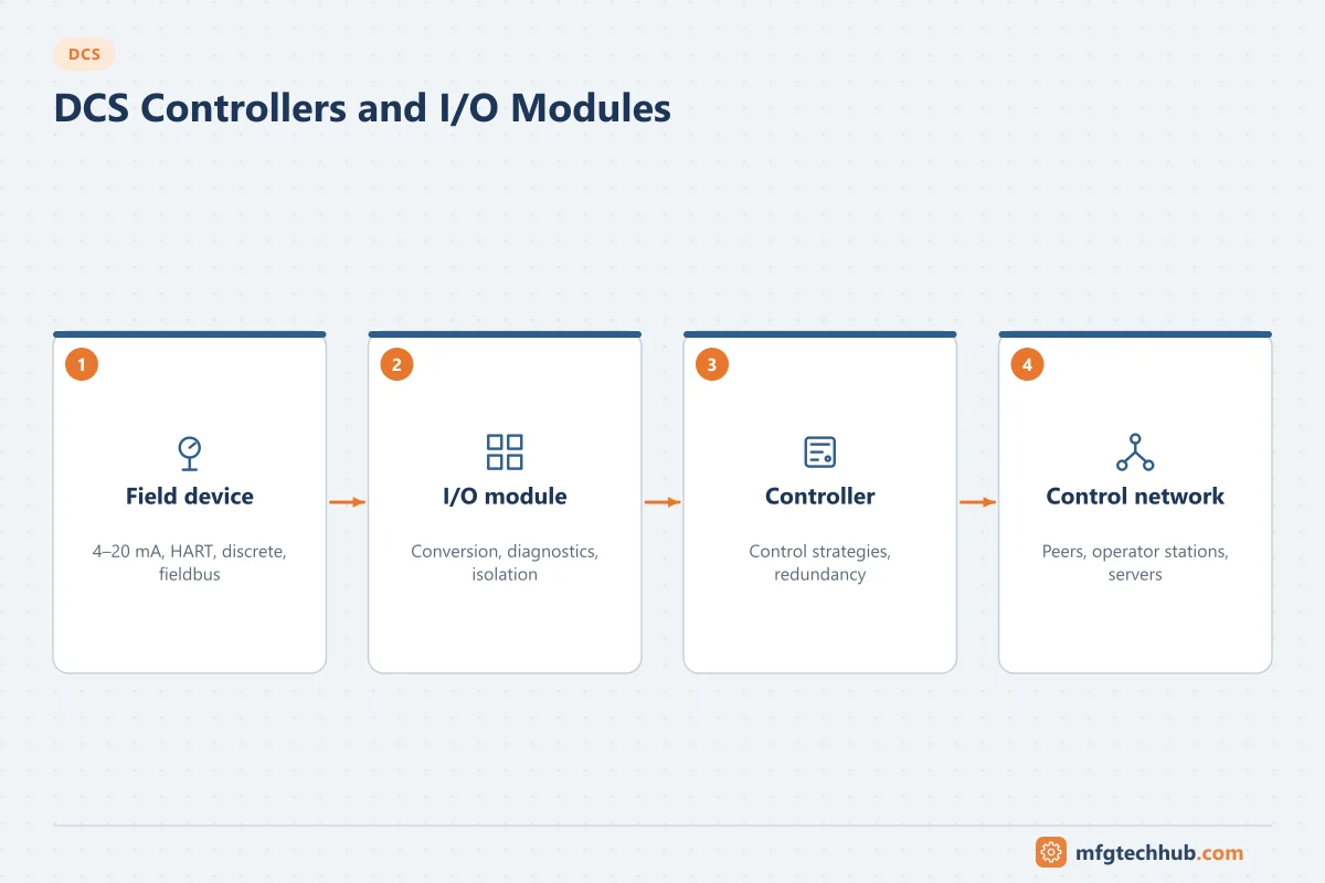
Some vendors call the controller with its I/O a control station. Yokogawa, for example, uses the term Field Control Station (FCS). The name differs but the function is the same. This page covers both the controller and its I/O.
What a DCS controller does
| Function | What happens in the controller |
|---|---|
| Input processing | Reads I/O values, applies scaling, checks signal status and HART or fieldbus diagnostics |
| Continuous control | Executes PID, cascade, ratio, feedforward and override strategies |
| Logic and interlocks | Permissives, process interlocks, motor and valve control logic |
| Sequences and batch phases | Step logic, phase logic for ISA-88 batch control |
| Output processing | Writes outputs, monitors readback and applies fail-safe states |
| Alarm detection | Generates process and diagnostic alarms with timestamps close to the source |
| Communication | Publishes values to operator stations and historians, exchanges data with peer controllers |
Control strategies are built from function blocks (for example AI, PID, AO) grouped into modules or control modules per loop or equipment item. Each module runs at a configured execution period, commonly from about 100 ms for fast flow and pressure loops to one second or more for slow temperature or level loops. See Setting Up Control Loops and DCS Control Strategies.
How control is divided between controllers
Distribution is what makes a DCS a DCS. A good allocation limits the effect of a controller failure and avoids timing problems:
- Allocate by process area or unit. One controller (pair) per unit or group of units, so a failure affects one area only.
- Keep a loop and its interlocks in one controller. A cascade split across two controllers depends on peer-to-peer communication, which adds delay and a failure point.
- Keep redundant equipment apart. Pump A and pump B, or duty and standby compressors, should be on different I/O cards and preferably different controllers, so one failure does not remove both.
- Separate safety functions. Safety instrumented functions run in a separate, certified safety system under IEC 61511, not in the basic process control controller.
- Leave spare capacity. Project specifications normally set a minimum spare CPU load, memory and I/O per controller for later changes. The actual percentages vary by company and project.
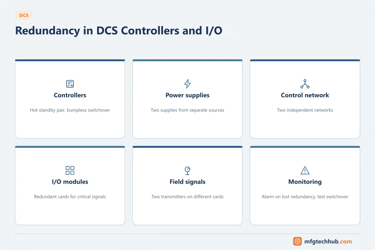
Redundancy
| Element | Typical redundancy approach |
|---|---|
| Controller | Primary and secondary controller in hot standby with automatic, bumpless switchover |
| Power supply | Two supplies fed from separate sources (for example UPS and a second feed) |
| Control network | Two independent networks or a fault-tolerant Ethernet design |
| I/O modules | Redundant I/O cards for critical signals; simplex I/O for the rest |
| Field signal | Two transmitters on different cards where a single failure must not trip or stop control |
Redundancy only helps if it is tested and monitored. The standby controller must be synchronised, a lost redundancy must raise a diagnostic alarm, and switchover should be tested during commissioning and after major changes. A plant that runs for months with an unnoticed failed standby has no redundancy at all.
I/O types
| I/O type | Signals | Notes |
|---|---|---|
| Analog input (AI) | 4–20 mA transmitters, often with HART | Detects open circuit and out-of-range signals; see Signal Conditioning |
| Analog output (AO) | 4–20 mA to valve positioners and drives | Output readback detects open circuits |
| Digital input (DI) | Switches, motor running feedback, limit switches | Line monitoring detects wire breaks where configured |
| Digital output (DO) | Motor start/stop, solenoid valves | Relay or solid-state outputs; check load ratings |
| Temperature | RTDs and thermocouples | Direct-connection cards avoid separate transmitters |
| Pulse / frequency | Turbine flowmeters, speed pickups | Counting done in the card |
| Fieldbus | FOUNDATION Fieldbus H1, PROFIBUS PA | Several devices per segment; see Fieldbus |
| Ethernet to the field | Ethernet-APL, PROFINET | Growing use for instruments and drives |
HART is the digital signal superimposed on the 4–20 mA loop. DCS I/O cards with HART pass-through let an asset management system read device diagnostics and configure transmitters remotely. See HART Protocol Explained.
Universal and configurable I/O
Traditional I/O cards have one fixed signal type, and each field cable passes through marshalling cabinets to reach the right card. Several vendors now offer software-configurable (universal) I/O or electronic marshalling: each channel is set to AI, AO, DI or DO in software. Examples include Emerson’s DeltaV CHARMs, Honeywell’s Universal I/O, Yokogawa’s N-IO and ABB’s Select I/O. The main benefit is on projects: I/O types that change late can be handled without rewiring, and marshalling is reduced.
Fail-safe output behaviour
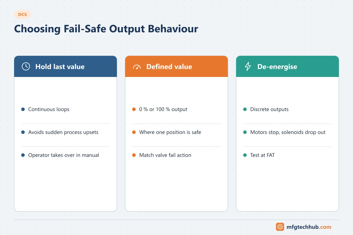
Decide for every output what happens when the controller, the I/O communication or the module fails:
| Option | When it fits |
|---|---|
| Hold last value | Continuous loops where a sudden change would upset the process |
| Go to a defined value (for example 0 % or 100 %) | Where one position is known to be safe |
| De-energise (discrete outputs) | Motors and solenoids that must stop or return to a safe position |
The choice must match the valve and actuator fail action (fail-open, fail-closed) and the process hazard analysis. Test fail-safe behaviour at FAT by removing controller power or communication.
Online changes and downloads
A DCS is expected to change without stopping the plant:
- Online download of changed modules without affecting other loops in the same controller.
- Bumpless changes: the output does not jump when a loop is downloaded or its mode changes.
- Version and change control: compare the running configuration with the engineering database before downloading, and follow a management of change process.
Some changes (controller firmware upgrades, some structural changes) still need a controller switchover or restart. Vendors document which changes are online.
Sizing a controller (illustrative)
A simple way to check controller loading before a project uses the vendor’s sizing tool, but the inputs are always the same:
- Count the I/O per type for the area.
- Count the modules (loops, motors, valves, sequences) and assign each an execution period.
- Use the vendor tool to estimate CPU load and memory.
- Compare with the project’s spare capacity requirement and split the area if needed.
A controller that is fully loaded on day one cannot take later changes, and faster execution periods than the process needs waste capacity.
Troubleshooting controllers and I/O
| Symptom | Likely cause | First check |
|---|---|---|
| One signal shows bad quality | Open wire, transmitter fault, channel fault | Loop current at the card; HART diagnostics |
| All signals on one card bad | Card failure, backplane or power | Card status LEDs and diagnostics; swap with a spare |
| Loops in one controller respond slowly | High CPU load, execution periods too fast | Controller load statistics |
| Redundancy lost alarm | Standby controller failed, not synchronised | Standby status; replace or restart the standby |
| Value different in controller and field | Wrong range, wrong HART range after transmitter change | Compare AI block range with transmitter range |
| Output does not move the valve | AO open circuit, positioner fault, valve stuck | AO readback, positioner diagnostics, valve stroke test |
Frequently asked questions
What is a control station in a DCS?
It is the controller with its I/O, power supplies and communication modules. Some vendors use “control station” (for example Yokogawa’s Field Control Station); others simply say controller. It executes the control strategies for a part of the plant.
Can a DCS controller run safety functions?
Safety instrumented functions normally run in a separate safety system (SIS) with certified logic solvers, as IEC 61511 requires independence between the basic process control system and the safety layer. Many vendors offer integrated but separate safety controllers for this purpose.
What is universal I/O?
I/O whose channel type (AI, AO, DI, DO) is configured in software instead of being fixed by the card. It reduces marshalling and makes late I/O changes easier.
Key takeaways
- The controller runs the plant; operator stations supervise it.
- Allocate controllers by process area, keep loops and their interlocks together, and separate redundant equipment.
- Redundancy must be monitored and tested to be real.
- Choose fail-safe output states deliberately and test them at FAT.
- Size controllers with spare capacity for later changes.
Related tutorials
Before you apply this in a plant: this article is for education. Always check the current edition of the relevant standards, the manufacturer's documentation for your exact product and version, and your site's procedures. Safety-related work needs qualified personnel. See our editorial policy.