
DCS System Integration and Instrument Calibration: Third-Party Interfaces, SIS, Testing and Calibration Management
On this page
A DCS rarely works alone. Compressors, packaged units, analysers, drives, electrical systems and safety systems all have their own controllers, and they must exchange data with the DCS reliably. At the same time, every measurement the DCS uses is only as good as the calibration of the instrument behind it. This guide covers both: integration of third-party systems, and calibration management for the instruments connected to the DCS.
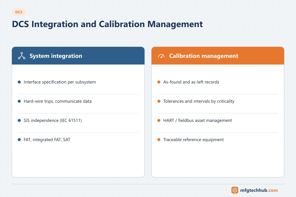
Part 1: Integrating third-party systems
Common interfaces
| Subsystem | Typical interface | Notes |
|---|---|---|
| Packaged units (compressors, chillers, water treatment skids) with their own PLC | Modbus TCP, OPC UA, PROFINET or EtherNet/IP, sometimes hard-wired signals | Hard-wire critical trips and permissives; use communication for monitoring. See Modbus and OPC UA |
| Variable speed drives and motor control centres | Fieldbus/Ethernet (PROFINET, EtherNet/IP, PROFIBUS), hard-wired start/stop | Define who controls in local/remote |
| Analysers | 4–20 mA, Modbus, OPC UA, analyser management systems | Include validity/maintenance status signals |
| Electrical systems (substations, protection relays) | IEC 61850 via gateways, Modbus, IEC 60870-5-104 | Often a separate electrical control system |
| Smart field devices | HART, FOUNDATION Fieldbus, PROFIBUS PA | Diagnostics feed asset management. See HART Protocol |
| Safety instrumented system (SIS) | Integrated or interfaced; trips hard-wired where required | See below |
| MES, historian, ERP | OPC UA, historian interfaces, via DMZ | See MES Integration |
The interface specification
Most integration problems come from undocumented assumptions. For each interface, agree and document:
- Signal list: tag, description, direction, data type, range and engineering units, scaling, update rate.
- Addressing: registers, node IDs or object addresses, including word order and bit numbering for Modbus.
- Control responsibility: which system controls what, local/remote handover, and command handshakes.
- Failure behaviour: what each side does on communication loss (hold, safe state, alarm); watchdog/heartbeat signals.
- Diagnostics and status: communication status tags, subsystem health, and how they appear to operators.
- Time synchronisation and timestamps. See Time Synchronisation in OT.
- Security: network zone, firewall rules, remote access by the vendor. See ISA/IEC 62443.
Integrating with the safety system
- Interfaced SIS: separate safety system exchanging status and bypass information with the DCS.
- Integrated SIS: safety controllers within the same vendor architecture, with defined separation.
Either way, the safety function must remain independent of the basic process control system as required by IEC 61511, and writes from the DCS to the SIS (for example bypass requests) must be restricted and managed. See Functional Safety.
Testing the integration
| Test | Purpose |
|---|---|
| Factory acceptance test (FAT) | DCS configuration tested against the specification, with simulated I/O |
| Integrated FAT | DCS tested together with subsystem controllers or simulators before shipment |
| Site acceptance test (SAT) | Complete system tested on site |
| Interface failure tests | Pull the cable, stop the subsystem controller, restart the DCS server: confirm alarms and failure behaviour |
See DCS Project Process.
Part 2: Instrument calibration management
Calibration basics in a DCS context
- Calibration compares an instrument’s output with a traceable reference and adjusts it if necessary. See Calibration and Standardisation.
- Record as-found (before adjustment) and as-left (after adjustment) results. As-found data shows whether the instrument was out of tolerance while in service.
- Define a tolerance per instrument based on process requirements, not just the manufacturer’s accuracy.
- Set intervals by criticality and history: shorten when as-found failures occur, extend when instruments stay stable.
- Use reference equipment calibrated with traceability to national standards. See Loop Calibrators.
Asset management with smart instruments
- DCS asset management systems use HART, FOUNDATION Fieldbus or PROFIBUS PA to read device configuration, diagnostics and status remotely.
- Diagnostics (sensor failure, drift alerts, valve positioner signatures) support condition-based maintenance and can justify interval changes.
- Configuration change tracking records changes to ranges and settings made through the asset management system.
- Remote reading of a device is not a calibration: calibration still requires a comparison with a reference standard.
Keeping DCS and instruments consistent
- A range change in the transmitter must be matched in the DCS input block (and vice versa) under management of change.
- Perform a loop check after calibration or replacement to confirm the DCS value matches the reference at several points.
- Put loops in manual, or bypass related alarms and interlocks under an authorised procedure, before calibration work. Safety instrument bypasses need special authorisation.
- In regulated industries, calibration records are GMP records. See Data Integrity (ALCOA+).
Calibration management software
Calibration management systems schedule work, hold procedures and tolerances, receive results from documenting calibrators, flag out-of-tolerance events for impact assessment, and report compliance. Integration with the CMMS keeps work orders and asset records aligned. See Instrument Preventive Maintenance and Calibration.
Troubleshooting
| Symptom | Likely cause | Check |
|---|---|---|
| Subsystem values wrong in DCS | Scaling, data type or word order mismatch | Interface specification vs actual configuration |
| Subsystem shows “comm fail” intermittently | Timeouts, network load, controller overloaded | Communication statistics, timeouts, network |
| DCS and field indication disagree | Range mismatch after calibration or replacement | Transmitter range vs DCS AI block |
| Frequent as-found failures on one instrument type | Wrong instrument for the application, installation problem, interval too long | Failure history; installation review |
| Process upset during calibration | Loop not in manual, interlock not bypassed under procedure | Calibration procedure and permits |
Frequently asked questions
How is a packaged unit PLC integrated with a DCS?
Usually through a communication interface such as Modbus TCP, OPC UA or an industrial Ethernet protocol for monitoring and non-critical commands, with critical trips and permissives hard-wired. An interface specification defines signals, scaling, control responsibility and failure behaviour.
What is the difference between as-found and as-left calibration?
As-found is the instrument’s performance before any adjustment, showing how it performed in service. As-left is its performance after adjustment. Both should be recorded.
Does HART diagnostics replace calibration?
No. HART and other smart-device diagnostics help detect problems and plan maintenance, but calibration still requires comparing the instrument with a traceable reference.
Key takeaways
- Integrate subsystems with a written interface specification covering signals, control responsibility, failure behaviour, diagnostics and security.
- Keep safety systems independent and restrict writes from the DCS.
- Test interfaces at FAT, integrated FAT and SAT, including failure cases.
- Manage calibration with tolerances, intervals, as-found/as-left records, traceable references and management of change.
Related tutorials
Before you apply this in a plant: this article is for education. Always check the current edition of the relevant standards, the manufacturer's documentation for your exact product and version, and your site's procedures. Safety-related work needs qualified personnel. See our editorial policy.