
DCS Networks: Topologies, Protocols, Redundancy and Design Rules
On this page
A DCS depends on its networks. Controllers exchange data with each other and with operator stations, I/O communicates with controllers, and the plant network carries data to historians and business systems. A network failure can blind operators or stop control, so DCS networks are designed with layers, redundancy and strict separation.
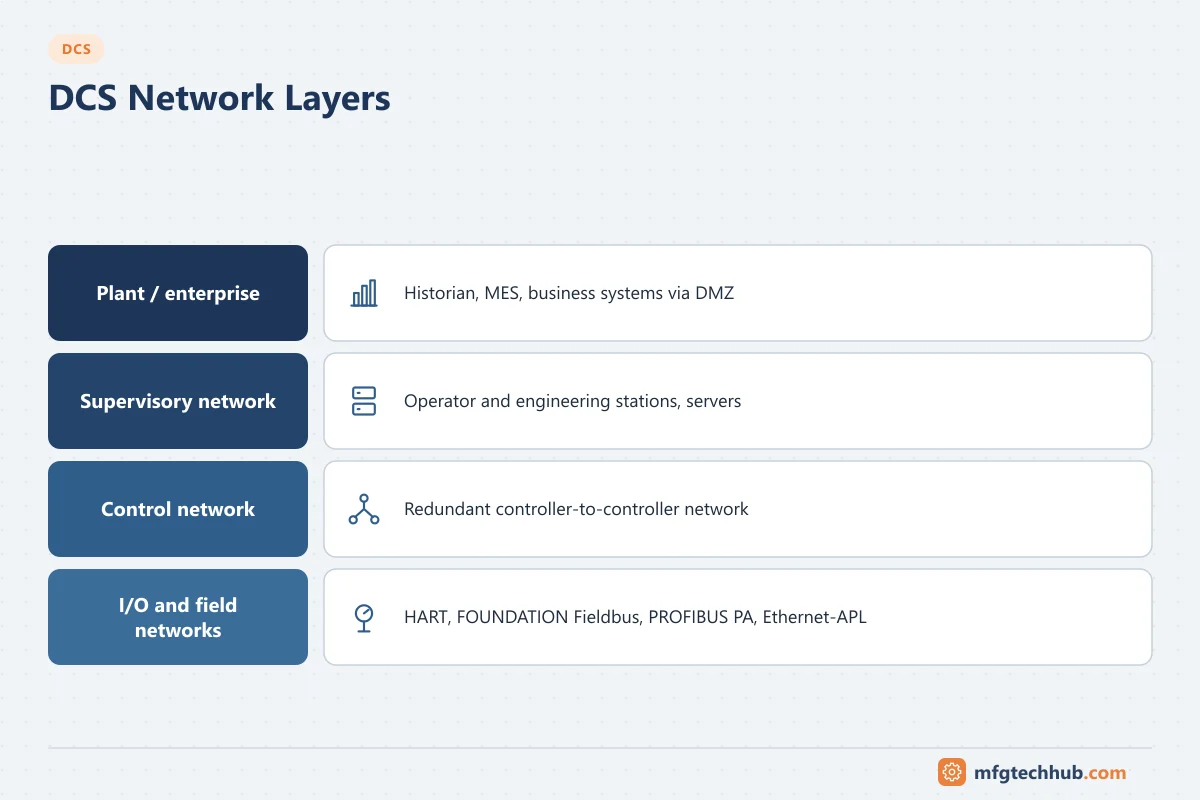
Network layers in a DCS
| Layer | Purpose | Typical technologies |
|---|---|---|
| Field network | Connect instruments and valves | 4–20 mA with HART, FOUNDATION Fieldbus H1, PROFIBUS PA, WirelessHART/ISA100, Ethernet-APL |
| I/O network | Connect remote I/O to controllers | Vendor I/O bus, PROFINET, EtherNet/IP, PROFIBUS DP, fibre links to remote cabinets |
| Control network | Controller-to-controller and controller-to-server communication | Redundant industrial Ethernet with vendor protocols |
| Supervisory network | Operator and engineering stations, servers | Ethernet, often on the same redundant infrastructure as the control network or a separate segment |
| Plant/DMZ | Historian replication, MES, remote access, patch and antivirus servers | Routed and firewalled networks; industrial DMZ |
The layers correspond to zones in an IEC 62443 security design: traffic between them passes through controlled conduits.
Field networks
- 4–20 mA with HART: still the most common. The analogue signal carries the measurement; HART adds digital configuration and diagnostics. HART-enabled I/O or multiplexers pass the digital data to asset management.
- FOUNDATION Fieldbus H1: fully digital, multi-drop segments (31.25 kbit/s) powered by the bus; supports control in the field on some systems. Segment design must consider power, device count, spur lengths and hazardous-area requirements (FISCO/Entity or high-power trunk concepts).
- PROFIBUS PA: similar physical layer to H1, connected to PROFIBUS DP via couplers or links; common in Europe and in PROFIBUS-based systems.
- WirelessHART / ISA100 Wireless: for monitoring points where cables are expensive; generally not used for fast or critical control.
- Ethernet-APL: two-wire Ethernet (10 Mbit/s) with power and intrinsic-safety options over long cable runs, carrying protocols such as PROFINET, EtherNet/IP, HART-IP and OPC UA directly to field devices.
See Industrial Communication Protocols and Industry 4.0 and Smart Instrumentation.
Topologies
| Topology | How it works | Strengths | Weaknesses |
|---|---|---|---|
| Star | Devices connect to a central switch | Simple, easy to troubleshoot | The central switch is a single point of failure unless duplicated |
| Redundant star (dual network) | Two independent star networks (A and B); each node has two network interfaces | No single point of failure; common in DCS control networks | Twice the switches and cabling |
| Ring | Switches connected in a loop; a redundancy protocol blocks one link until a failure | Tolerates a single cable or switch failure with fewer cables | Recovery time depends on the protocol |
| Bus / trunk-and-spur | Devices on a shared cable (fieldbus segments) | Low cabling for field devices | Segment faults can affect all devices; design rules must be followed |
| Mesh | Multiple paths (common in wireless networks) | Self-healing | Complex; latency varies |
Many DCS vendors specify their own supported topologies and switch models. Follow the vendor’s network design guide; unsupported designs can cause subtle performance problems.
Redundancy protocols
| Protocol | Standard | Typical recovery | Notes |
|---|---|---|---|
| RSTP | IEEE 802.1D/802.1Q | Hundreds of milliseconds to seconds depending on topology | Common in IT and general industrial networks |
| MRP | IEC 62439-2 | Up to 200 ms, 500 ms depending on configuration (a 10 ms profile also exists) | Ring redundancy, common with PROFINET |
| DLR (Device Level Ring) | ODVA | Fast ring recovery at device level | EtherNet/IP networks |
| PRP | IEC 62439-3 | Zero recovery time (frames sent over two independent networks) | Used for demanding applications, including substations |
| HSR | IEC 62439-3 | Zero recovery time in a ring | Nodes need HSR support or RedBoxes |
| Vendor-specific | — | Varies | Many DCS control networks use vendor redundancy mechanisms |
Controller-level redundancy (primary/backup controllers, dual network interfaces) works together with network redundancy. See Traditional vs Modern DCS Architecture.
Time synchronisation
Accurate time stamps are essential for sequence-of-events analysis, alarms and historian data.
- NTP is typically used for servers and workstations (millisecond-level accuracy is sufficient for most process events).
- IEEE 1588 PTP provides sub-microsecond accuracy where required (for example in power systems and some high-speed applications).
- GPS/GNSS clocks provide the reference, usually with redundancy.
Controllers, servers and field devices must share the same time source; unsynchronised clocks make incident investigation difficult.
Design rules for DCS networks
- Use the vendor’s approved architecture and switches for the control network.
- Separate control, supervisory and plant networks; put a firewall and DMZ between the DCS and business networks. Do not route business traffic through control switches.
- Redundancy without common-mode failures: route A and B networks through different cable paths and power supplies.
- Fibre between buildings and for long runs, to avoid ground potential differences and electromagnetic interference.
- Manage multicast where protocols use it (IGMP snooping), and apply QoS where the vendor recommends it.
- Capacity planning: check controller communication loads, historian collection rates and peer-to-peer traffic, especially during upsets when alarm and event traffic spikes.
- Document IP addressing, VLANs, switch configurations and firewall rules; back them up.
- Monitor switch health, port errors and redundancy status; a failed redundant path must alarm, or the system silently loses its protection.
Troubleshooting network problems
| Symptom | Possible causes | Checks |
|---|---|---|
| Operator displays freeze intermittently | Network storms, duplicate IP addresses, overloaded server | Switch port statistics, broadcast levels, server CPU |
| Redundancy alarm on one network | Cable, switch or interface failure | Link status on both ends, switch logs |
| Fieldbus segment devices drop out | Power supply, termination, spur length, water in junction boxes | Segment diagnostics (voltage, noise, signal level), physical inspection |
| Historian gaps | Network interruption between DCS and historian, buffering disabled | Interface logs, store-and-forward configuration |
| Slow engineering downloads | Large downloads during peak load, misconfigured switch | Vendor diagnostics, switch configuration |
Frequently asked questions
Why do DCS networks use two independent networks?
A dual (A/B) network removes single points of failure: every node connects to both networks, so a failed cable, switch or interface does not interrupt communication. This is a standard feature of most DCS control networks.
Can the DCS control network share switches with the business network?
It should not. Sharing infrastructure exposes the control system to business traffic, misconfigurations and cyber threats. Use separate infrastructure with a firewalled DMZ for data exchange.
What is the difference between PRP and MRP?
MRP is a ring protocol that blocks one link and reconfigures after a failure, with a short recovery time. PRP sends every frame over two independent networks at the same time, so there is no recovery delay when one network fails.
Key takeaways
- DCS networks are layered: field, I/O, control, supervisory and plant/DMZ.
- Redundant topologies and protocols (dual networks, rings, PRP) avoid single points of failure.
- Follow vendor network guidelines, separate networks, synchronise time and monitor redundancy status.
Related tutorials
Before you apply this in a plant: this article is for education. Always check the current edition of the relevant standards, the manufacturer's documentation for your exact product and version, and your site's procedures. Safety-related work needs qualified personnel. See our editorial policy.