
HART Protocol Explained: Digital Data on 4-20 mA, Commands, Multidrop, WirelessHART and HART-IP
On this page
HART (Highway Addressable Remote Transducer) adds digital communication to the classic 4–20 mA analog signal. It is the most widely installed digital protocol in process instrumentation: most modern pressure, temperature, flow and level transmitters and many valve positioners support it. The technology is managed by the FieldComm Group.
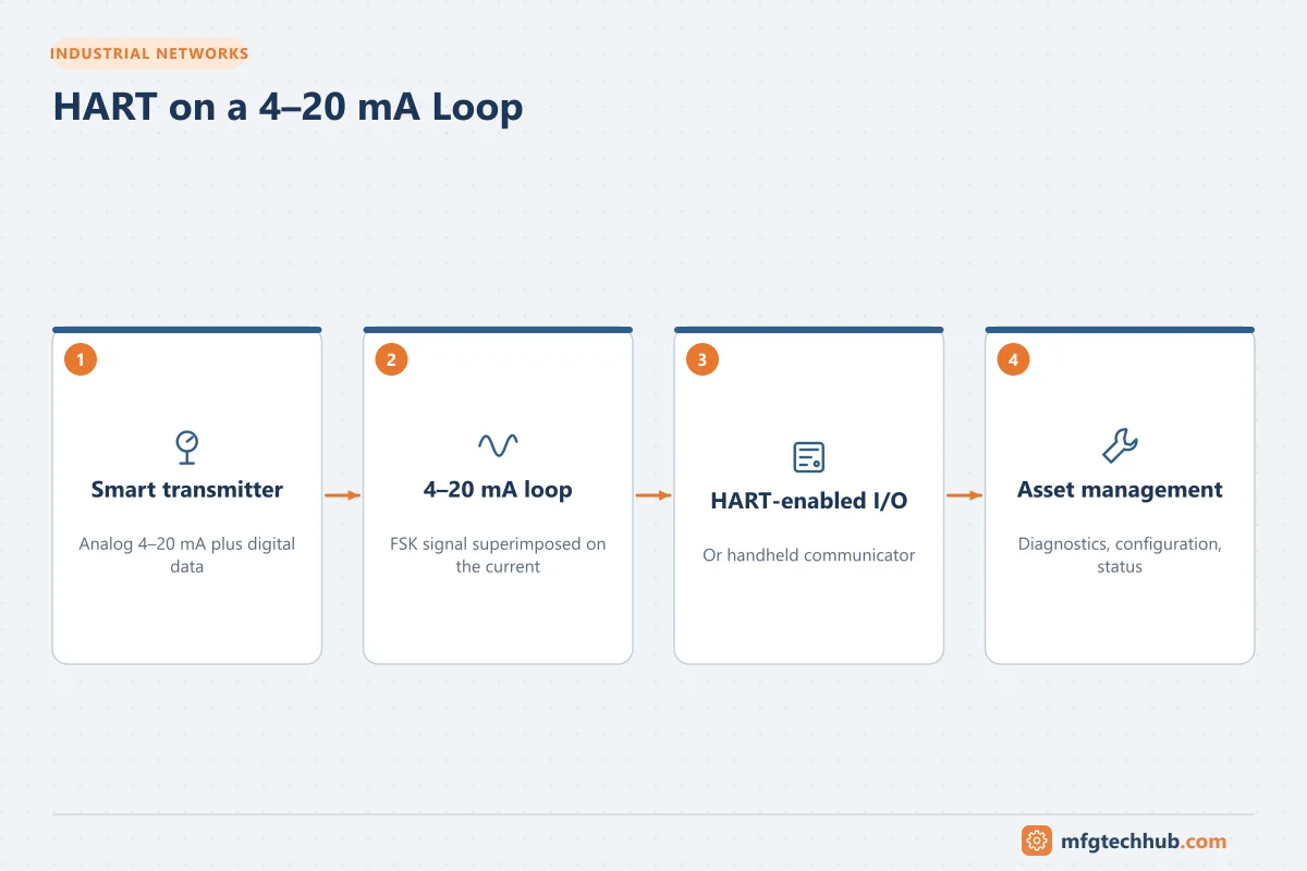
HART’s great advantage is compatibility: the 4–20 mA signal keeps working exactly as before, while configuration, diagnostics and extra measurements travel digitally on the same two wires.
How HART works on a 4–20 mA loop
- HART uses frequency shift keying (FSK) based on the Bell 202 standard: 1,200 Hz represents a 1 and 2,200 Hz represents a 0, at 1,200 bit/s.
- The signal is a small sine wave (about ±0.5 mA) superimposed on the loop current. Its average value is zero, so it does not disturb the analog measurement.
- A loop resistance is needed to develop a readable HART voltage; typically at least 250 Ω in the loop (the input resistor of an analog input card often provides it). Too little resistance, for example a loop powered directly from a low-impedance supply, prevents communication.
See the 4–20 mA calculator and Loop Calibrators.
Masters and devices
HART is a master–slave protocol:
| Role | Example |
|---|---|
| Primary master | Control system with HART-enabled I/O, or asset management system via multiplexers |
| Secondary master | Handheld communicator or laptop modem connected in the field |
| Field device (slave) | Transmitter, positioner, analyser |
Two masters can communicate with a device at the same time, so a technician can use a handheld while the control system is connected.
What data HART provides
| Data | Examples |
|---|---|
| Dynamic variables | PV (primary variable), SV, TV, QV; for example, a Coriolis meter’s mass flow, density, temperature and totaliser |
| Loop current and percent of range | Lets you compare digital and analog values |
| Device status | Device malfunction, configuration changed, output saturated, output fixed, more status available |
| Configuration | Tag, range (LRV/URV), units, damping, transfer function, sensor information |
| Diagnostics | Sensor health, plugged impulse line detection, valve signatures (positioners), electronics temperature |
Commands
| Command group | Content | Examples |
|---|---|---|
| Universal commands | Supported by every HART device | Read unique identifier (command 0), read primary variable (command 1), read loop current and dynamic variables (command 3) |
| Common practice commands | Supported by many devices | Set range values, set damping, loop test |
| Device-specific commands | Unique to a manufacturer’s device | Advanced diagnostics, special configuration |
To access device-specific functions, host systems use device descriptions: DD/EDD files, DTMs (FDT technology) or the newer FDI packages.
Operating modes
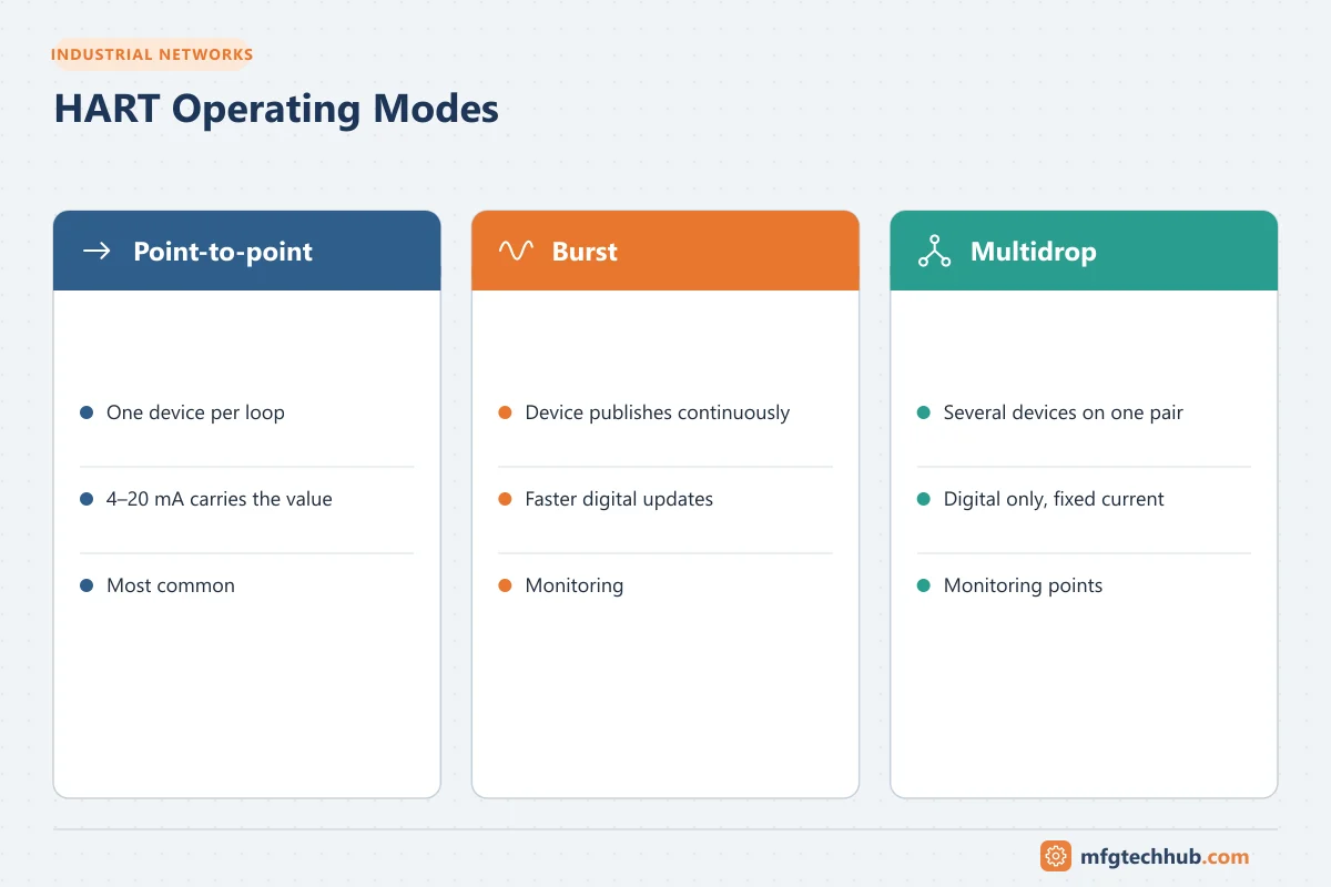
- Point-to-point (standard): one device per loop; the analog 4–20 mA carries the measurement, HART carries additional data. This is by far the most common mode.
- Burst mode: the device continuously broadcasts selected data without being polled, for faster digital updates.
- Multidrop: several devices share one pair of wires, each with its own polling address; the analog current is fixed at a low value (typically 4 mA) and all data is digital. Used for monitoring applications, rarely for control because the update rate is slow.
HART versions, WirelessHART and HART-IP
| Technology | Summary |
|---|---|
| HART 5, 6, 7 | Successive revisions adding features such as longer tags, more status information and, with HART 7, WirelessHART |
| WirelessHART | Wireless mesh network (IEEE 802.15.4-based, 2.4 GHz) using a gateway; standardised as IEC 62591; used for monitoring points where cables are costly. See Wireless Sensor Networks |
| HART-IP | Carries HART commands over IP networks, used by multiplexers, gateways and, increasingly, Ethernet-APL devices |
Getting value from HART data
Many plants use HART only for commissioning with a handheld. The digital data remains unused in operation because the control system reads only the 4–20 mA. Options to use it:
- HART-enabled analog I/O in the DCS or PLC passes HART data to the host and to asset management software.
- HART multiplexers connect to existing loops (in marshalling cabinets) and feed asset management without changing the control system.
- WirelessHART adapters retrofit to wired devices and send their HART data wirelessly.
Uses: remote configuration and verification, predictive maintenance (device and valve diagnostics), fewer unnecessary field trips, calibration management, and NAMUR NE 107 status reporting. See Industry 4.0 and Smart Instrumentation.
Troubleshooting HART communication
| Symptom | Likely causes | Checks |
|---|---|---|
| Handheld cannot communicate | Loop resistance too low, no loop power, communicator connected across the wrong points | Measure loop resistance; connect across the resistor or device terminals; confirm loop current |
| Intermittent communication | Electrical noise, long cable with high capacitance, poor shielding, bad connections | Cable length and type, shield grounding, noise sources |
| Communicates on the bench but not in the loop | Barrier or isolator does not pass HART; filter capacitors in I/O | Check that barriers, isolators and I/O cards are HART-compatible |
| Analog value does not match digital PV | Range mismatch between device and host, loop current fixed (loop test or multidrop mode), analog output trim needed | Compare LRV/URV in device and host; check “output fixed” status; perform D/A trim |
| Device not found in multidrop | Duplicate polling addresses | Assign unique addresses |
Frequently asked questions
Does HART affect the 4–20 mA measurement?
No. The HART signal is a small, fast alternating signal with an average of zero, so a properly designed analog input filters it out and reads the same current as without HART.
What loop resistance is needed for HART?
Typically at least about 250 Ω in the loop, within the maximum allowed by the transmitter’s supply voltage and minimum operating voltage. Check the device manual for the exact range.
Is HART still relevant with Ethernet-APL?
Yes. The installed base of HART devices is very large and will remain in service for many years. HART-IP also lets HART commands and device descriptions be used over IP-based networks, including Ethernet-APL.
Key takeaways
- HART superimposes digital FSK communication on the 4–20 mA signal without disturbing it.
- It provides extra variables, configuration, status and diagnostics through universal, common practice and device-specific commands.
- Most plants underuse HART data; HART-enabled I/O, multiplexers and asset management unlock it.
- Communication problems are usually loop resistance, noise, cabling or HART-incompatible barriers.
Related tutorials
Before you apply this in a plant: this article is for education. Always check the current edition of the relevant standards, the manufacturer's documentation for your exact product and version, and your site's procedures. Safety-related work needs qualified personnel. See our editorial policy.