
Modbus RTU and Modbus TCP Explained: Registers, Function Codes, Wiring and Troubleshooting
On this page
Modbus is the most widely supported industrial protocol. It was published by Modicon in 1979 for its PLCs, and its simplicity has kept it alive: power meters, VFDs, analysers, flow computers, gateways and almost every SCADA system speak it. It is now maintained by the Modbus Organization, and its specifications are freely available.
Its simplicity is also its weakness: no data types, no descriptions, no security in the original protocol. Integration problems almost always come from addressing, data formats and serial wiring. This guide explains all three.
How Modbus communication works
Modbus uses a client/server (historically master/slave) request–response model:
- The client (for example a PLC, SCADA or gateway) sends a request: read 10 holding registers starting at address 100 from device 5.
- The server (the field device) replies with the data or an exception code.
- Servers never send data unless asked.
The same application messages (the PDU) run over different transports:
| Variant | Transport | Framing and checking |
|---|---|---|
| Modbus RTU | Serial, usually RS-485 (sometimes RS-232) | Binary frames; CRC-16; frames separated by silent intervals of 3.5 character times |
| Modbus ASCII | Serial | ASCII characters; LRC checksum; rarely used today |
| Modbus TCP | Ethernet, TCP port 502 | MBAP header; TCP provides error checking |
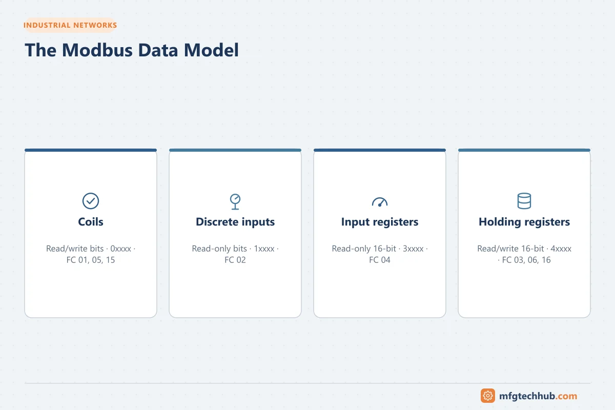
The data model
| Table | Access | Size | Typical use | Conventional reference |
|---|---|---|---|---|
| Coils | Read/write | 1 bit | Commands, digital outputs | 0xxxx (00001–) |
| Discrete inputs | Read only | 1 bit | Status, digital inputs | 1xxxx (10001–) |
| Input registers | Read only | 16 bits | Measurements | 3xxxx (30001–) |
| Holding registers | Read/write | 16 bits | Setpoints, configuration, and often measurements too | 4xxxx (40001–) |

The addressing trap
Device manuals often list registers using the conventional reference (for example 40001), but the protocol itself uses a zero-based address within each table. So:
- “40001” in a manual = holding register address 0 in the request
- “40108” = address 107
Some manuals list zero-based addresses directly, some one-based, and some add their own offsets. If every value appears shifted by one register, this is almost always the cause. Confirm with a known register (for example a serial number or a fixed value).
Function codes
| Code | Function |
|---|---|
| 01 | Read coils |
| 02 | Read discrete inputs |
| 03 | Read holding registers |
| 04 | Read input registers |
| 05 | Write single coil |
| 06 | Write single register |
| 15 (0x0F) | Write multiple coils |
| 16 (0x10) | Write multiple registers |
| 23 (0x17) | Read/write multiple registers |
A single read is limited (for example up to 125 registers for function 03/04, 2,000 coils for function 01). Group consecutive registers into as few requests as possible to reduce poll time.
32-bit values, floats and byte order
Registers are 16 bits. Larger values use two (or four) consecutive registers:
- 32-bit integers and IEEE 754 floating-point values use two registers.
- 64-bit values (for example energy counters) may use four.
The order of the two registers (and sometimes of the bytes within them) is not defined consistently between manufacturers. A value such as 230.5 V can appear as a meaningless huge or tiny number if the order is wrong.
| Symptom | Likely fix |
|---|---|
| Float value nonsensical but changes plausibly with the process | Swap word order |
| Still wrong | Try byte swap within words |
| Integer value looks 65,536 times too big or too small | Word order or wrong register pair |
Also check scaling: many devices send integers with an implied multiplier (for example value × 10 or × 100) documented in the manual. The Engineering Unit Converter helps check converted values.
Modbus RTU and RS-485 wiring
RS-485 is a differential, multi-drop serial bus. Most Modbus RTU problems are physical:
| Rule | Why |
|---|---|
| Daisy-chain topology (no star wiring, short stubs only) | Reflections corrupt data on long stars and stubs |
| Termination (typically 120 Ω) at both ends of the bus only | Prevents reflections; missing or extra terminators cause errors |
| Biasing (fail-safe resistors) at one point | Keeps the idle line in a defined state |
| Twisted-pair shielded cable with common/reference conductor | Noise immunity; common reference avoids exceeding common-mode limits |
| Shield grounded according to site practice (often at one end) | Avoids ground loops |
| Consistent polarity (A/B, D+/D−) | Manufacturers label A/B inconsistently; if nothing communicates, try swapping |
| Unit load limit | A standard RS-485 segment supports 32 unit loads; more devices need low-load transceivers or repeaters |
| Distance vs speed | Around 1,200 m is possible at lower baud rates; higher speeds need shorter runs |
Serial settings must match on every device: baud rate (9,600 and 19,200 are common), data bits, parity and stop bits. The Modbus specification defines even parity as the default; many devices are shipped with other settings (for example 8N1). Each device on the bus needs a unique address from 1 to 247.

Modbus TCP
Modbus TCP wraps the same PDU in a 7-byte MBAP header:
| Field | Purpose |
|---|---|
| Transaction ID | Matches responses to requests |
| Protocol ID | Always 0 for Modbus |
| Length | Number of following bytes |
| Unit ID | Identifies a device behind a gateway (often ignored by native TCP devices, or must be 1 or 255 for some) |
Gateways convert Modbus TCP to RTU; the Unit ID then selects the serial device. Gateway exception codes 0x0A (path unavailable) and 0x0B (target device failed to respond) point to problems on the serial side.
Performance tips: limit simultaneous TCP connections to small devices (many support only a few), reuse connections rather than reconnecting for every poll, and set sensible timeouts.
Exception codes
| Code | Meaning | Typical cause |
|---|---|---|
| 01 | Illegal function | Device does not support that function code |
| 02 | Illegal data address | Register does not exist (often the off-by-one issue or a read spanning into an unmapped range) |
| 03 | Illegal data value | Value out of range or wrong quantity |
| 04 | Server device failure | Internal device error |
| 06 | Server device busy | Retry later |
| 0A / 0B | Gateway path unavailable / target failed to respond | Serial side problem behind a gateway |
No response at all (timeout) is different from an exception: it usually means wrong address, wrong serial settings, wiring problems or an unreachable IP.
Security
Classic Modbus has no authentication or encryption: any device on the network can read and write. Protect it by:
- Keeping Modbus devices in segmented control zones behind firewalls; never exposing port 502 to the internet
- Restricting which hosts may connect (firewall rules, device access lists where available)
- Using a gateway or edge device to translate to secure protocols (OPC UA, MQTT over TLS) for higher-level systems
The Modbus Organization has also published a Modbus/TCP Security specification that adds TLS (on port 802); check whether your devices support it. See Industrial Network Design for OT Engineers.
Troubleshooting checklist
- Serial: baud rate, parity, stop bits and device address match? Polarity? Termination at both ends only? Common reference connected?
- TCP: can you ping the device? Is port 502 reachable? Is the connection limit exceeded? Correct Unit ID?
- Addressing: off-by-one? Correct table (holding vs input registers)?
- Data format: word/byte order, scaling, signed vs unsigned?
- Timing: timeout long enough for slow devices? Poll interval realistic for the number of devices and registers on a serial bus?
- Tools: a Modbus test client or a serial analyser shows the raw requests and responses, which settles most disputes quickly.
Frequently asked questions
What is the difference between Modbus RTU and Modbus TCP?
They use the same data model and function codes. RTU runs over serial lines (usually RS-485) with binary framing and a CRC; TCP runs over Ethernet on port 502 with an MBAP header. Gateways convert between them.
Why are my Modbus values off by one register?
Because manuals often use one-based references (40001) while the protocol uses zero-based addresses (0). Subtract one, or configure your client’s addressing mode to match the manual.
How many devices can be connected on a Modbus RTU network?
Up to 247 addresses are available, but a standard RS-485 segment supports 32 unit loads. More devices need low-load transceivers or repeaters, and polling time increases with the number of devices.
Key takeaways
- Modbus is simple and universal: four data tables, a few function codes, RTU over RS-485 or TCP on port 502.
- Most problems are addressing offsets, word order and scaling, or RS-485 wiring and settings.
- Classic Modbus has no security; protect it with segmentation and translate to secure protocols for higher levels.
Related tutorials
Before you apply this in a plant: this article is for education. Always check the current edition of the relevant standards, the manufacturer's documentation for your exact product and version, and your site's procedures. Safety-related work needs qualified personnel. See our editorial policy.