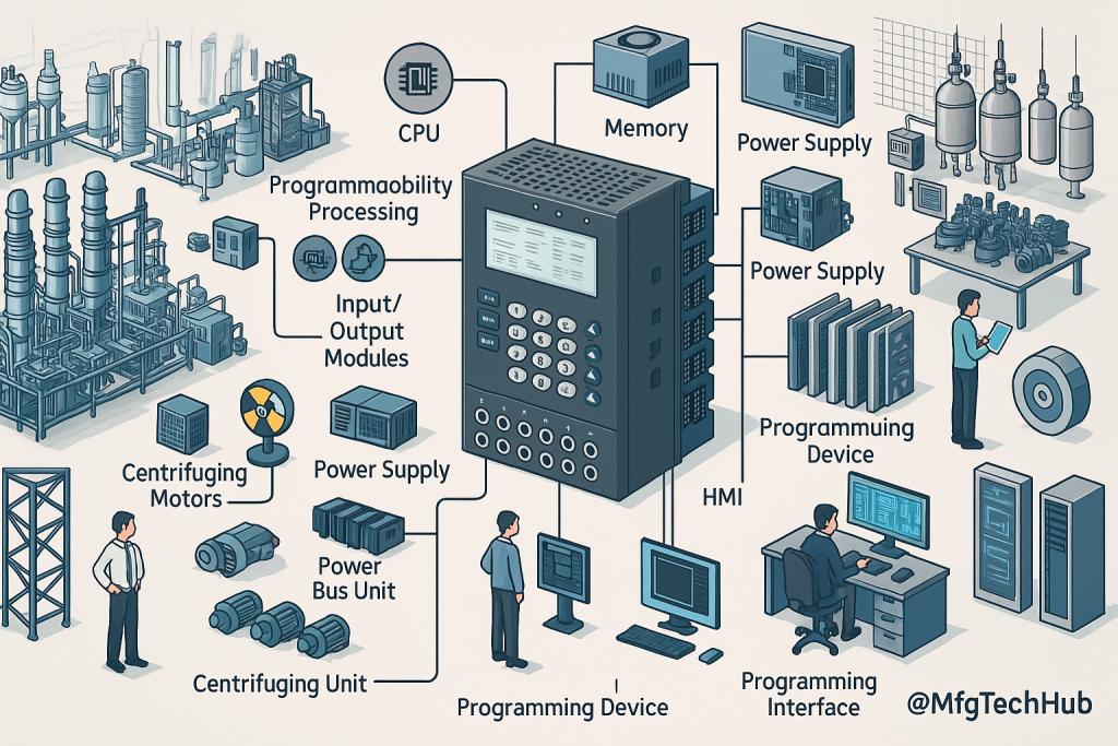
Basic Components of a Programmable Logic Controller (PLC)
A Programmable Logic Controller (PLC) is a specialized industrial computer designed for automation and control applications. It processes inputs, executes a control program, and generates outputs to manage machinery, manufacturing lines, and various industrial processes. To fully understand how PLCs function, it is essential to explore their key components and how they work together.

PLCs are designed to replace hardwired relay logic systems, providing a flexible, scalable, and highly reliable solution for industrial control. Each PLC consists of multiple essential components, each playing a specific role in its operation. This article will explore the fundamental components of a PLC, their functions, and how they interact to achieve seamless automation.
1. Central Processing Unit (CPU) – The Brain of the PLC

The Central Processing Unit (CPU) is the core of a PLC, responsible for executing programmed instructions, processing data, and controlling input/output (I/O) operations. It functions similarly to a computer processor but is optimized for real-time control and industrial automation.
Key Functions of the CPU:
- Receives input signals from sensors and field devices
- Processes logic-based control instructions
- Generates output commands for actuators, motors, and other industrial devices
- Performs diagnostic checks to detect faults or system errors
- Stores and runs the PLC program (logic written by engineers)
Example:
➡️ In an automated conveyor system, the CPU processes sensor input signals to determine when to start/stop the conveyor, activate robotic arms, and adjust speed based on production demand.
Types of CPUs in PLCs:
- Single-Processor CPUs: Handle basic control tasks
- Multi-Core CPUs: Used for complex automation and high-speed processing
- Redundant CPUs: Provide backup in critical applications (e.g., power plants, chemical processing)
The speed and efficiency of the CPU determine how quickly the PLC can process data and respond to changes in the system.
2. Memory – Storing Program Logic and Data
PLC memory is crucial for storing:
- Program code (user-defined logic)
- Real-time operational data
- System diagnostics and fault logs
Types of PLC Memory:
- ROM (Read-Only Memory) – Stores permanent system firmware and operating instructions
- RAM (Random Access Memory) – Holds temporary program execution data and real-time variables
- EEPROM/Flash Memory: Non-volatile storage for retaining PLC programs after power loss
Example:
➡️ In a bottling plant, the PLC memory stores logic for filling bottles, capping, labeling, and conveyor speed control. EEPROM ensures the program is restored after power failure.
3. Input/Output (I/O) Modules – Connecting the PLC to Field Devices
I/O modules are the bridge between the PLC and the physical world. They allow the PLC to receive inputs and send outputs to devices.
A. Input Modules – Receiving Data
➡️ Collect signals from:
- Sensors (temperature, pressure, proximity)
- Push buttons and switches
- Encoders and limit switches
Example: In a manufacturing line, the PLC gets input from a proximity sensor to detect a product’s presence for the next operation.
B. Output Modules – Sending Control Commands
➡️ Control devices like:
- Motors and conveyor belts
- Valves and solenoids
- Lights, alarms, and displays
Example: In an automated warehouse, the PLC activates robotic arms to pick and place items based on the program sequence.
4. Power Supply – Providing the Necessary Voltage
The power supply unit converts standard AC voltage into low-voltage DC power required by the PLC components.
Common PLC Power Supply Ratings:
- 24V DC – Common in industrial use
- 120V or 240V AC – Used in large-scale systems
- Redundant Power Supplies – For mission-critical systems like hospitals or nuclear plants
Example:
➡️ In a food processing plant, a 24V DC power supply ensures uninterrupted PLC operation, avoiding downtime from power fluctuations.
5. Communication Ports and Networking – Enabling System Connectivity
Modern PLCs communicate with HMIs, SCADA systems, and IIoT platforms using various protocols.
Common PLC Communication Protocols:
- Ethernet/IP – High-speed industrial networking
- Modbus – Device communication
- Profibus/Profinet – Factory automation and robotics
- OPC UA – Cloud and IIoT integration
Example:
➡️ In a smart factory, PLCs use wireless communication with IoT sensors to optimize energy, track health, and prevent failures.
6. Programming Device – Writing and Uploading Control Logic
Engineers use programming software on a PC to develop and upload PLC programs.
Common Programming Tools:
- Siemens TIA Portal
- Rockwell Studio 5000
- Mitsubishi GX Works
Example:
➡️ In a packaging system, Ladder Logic is programmed to control box filling, sealing, and labeling.
7. Human-Machine Interface (HMI) – User Control Panel
An HMI provides real-time visualization and interaction with the PLC system.
Common HMI Features:
- Touchscreen or button control
- Graphical displays of operations
- Alarms and status updates
Example:
➡️ In a power plant, operators use the HMI to adjust turbine speed, monitor power output, and respond to fault alerts.
Conclusion
PLCs are modular control systems made of essential components that work together to automate industrial processes. These include the CPU, memory, I/O modules, power supply, communication ports, programming device, and HMI.
As industries move toward smart automation, PLCs will evolve to become more intelligent, connected, and integrated with IIoT and AI. Understanding these components is key to designing, programming, and maintaining modern automation systems.
